GMS:Solids to Layered Mesh
The Solids → Layered Mesh command in the Solids menu can be used to quickly build a 3D finite element mesh that matches the stratigraphy defined by a set of solids. This option is similar to the Boundary Matching option of the Solids → MODFLOW command except it results in a layered 3D finite element mesh that honors the horizontal boundaries of the stratigraphic layers defined by a set of solids. The steps involved in using the Solids → Layered Mesh command are as follows:
1. Create a 2D Projection Mesh
The first step is to create a 2D projection mesh. This mesh represents a plan view of the 3D mesh. Each triangle in the 2D mesh will result in a column of 3D wedge elements and each quadrilateral in the 2D mesh will result in a column of 3D hexahedral elements. The 2D mesh can be refined around well locations if desired. This mesh is typically created using the Map module as part of the FEMWATER conceptual model.
2. Create the Solids
The next step is to create the solids defining the stratigraphy. The boundary of the solids should be slightly larger than the 2D projection mesh.
3. Assign layer ranges to the Solids
As is the case with the Solids → MODFLOW Boundary Matching option, a layer range should be assigned to each of the solids. There is one significant difference in assigning layer ranges with the Solids → Layered Mesh command is that every layer in the 3D mesh must be present in the solids. There cannot be "inactive" mesh elements similar to "inactive" grid cells.
4. Solids → Layered Mesh Command
Unlike the Solids → MODFLOW Boundary Matching option, it is not necessary to create a 3D mesh before selecting the Solids → Layered Mesh command. The 3D mesh is automatically generated. Each element in the 2D projection mesh is extruded into a vertical column of cells and the solids are used to assign the elevations to the nodes. The material ids are assigned to the 3D elements by finding the solid that encompasses the centroid of each 3D element assigning the material id of that solid to the element.
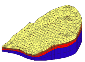
Sample Mesh
A sample mesh created with the Solids → Layered Mesh option is shown below. Note that the solids boundaries are preserved at the tops and bottoms of the solids but the transition along the edges of the solids can be irregular.
Related Topics
GMS – Groundwater Modeling System | ||
|---|---|---|
| Modules: | 2D Grid • 2D Mesh • 2D Scatter Point • 3D Grid • 3D Mesh • 3D Scatter Point • Boreholes • GIS • Map • Solid • TINs • UGrids | |
| Models: | FEFLOW • FEMWATER • HydroGeoSphere • MODAEM • MODFLOW • MODPATH • mod-PATH3DU • MT3DMS • MT3D-USGS • PEST • PHT3D • RT3D • SEAM3D • SEAWAT • SEEP2D • T-PROGS • ZONEBUDGET | |
| Aquaveo | ||
