GMS:Horizons Applications

The horizons method has been applied at a variety of sites to construct solid models of the subsurface. This page highlights example applications of the Horizons Method.
Contents
Modeling a Slope Failure
In this example a combination of boreholes, user-defined cross sections, and TINs were used to create solids at a site with a slope failure.
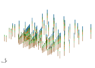
Borehole data
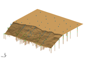
Surface elevations
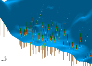
Failure surface
User defined cross sections
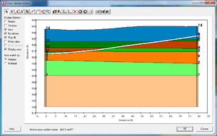
One user cross section
Zoomed in on cross sections
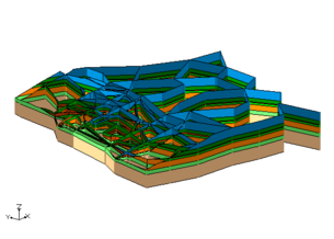
Solids created from user data
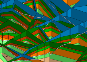
Cross sections from solids
Zoomed in on cross sections


Vertical Boundary Between Solids
In this application, the project required creating a set of solids where there would be distinct materials below a river bed compared to the other materials in the study area. The following cross section shows what a project wanted to create.

Primary TINs
To create solids that would match this cross section, create two different primary tins and executed the Horizons→Solids command for each primary TIN. The first TIN covered the area of the river and the second TIN covered the remainder of the study area as show in the images below.


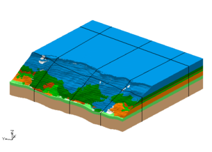
Solids
There are now TINs that defined the top elevations of the horizon surfaces. There were three TINs used in the area around the river and there were four TINs used the remainder of the study area. Solids were created for the river area using the first TIN as the primary TIN. Solids were also created in remainder of the study area by using the second TIN as the primary TIN. Notice the the bottom most material matches in both sets of solids. This is because the same TIN with that horizon was used when creating both sets of solids.


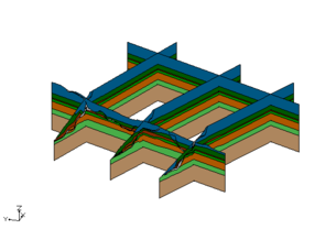
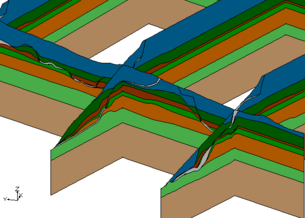
Cross Sections from Solids
These images show the solids together and cross section cut through the solids. Again notice how the bottom most material matches across both sets of solids.


| GMS – Groundwater Modeling System | ||
|---|---|---|
| Modules: | 2D Grid • 2D Mesh • 2D Scatter Point • 3D Grid • 3D Mesh • 3D Scatter Point • Boreholes • GIS • Map • Solid • TINs • UGrids | |
| Models: | FEFLOW • FEMWATER • HydroGeoSphere • MODAEM • MODFLOW • MODPATH • mod-PATH3DU • MT3DMS • MT3D-USGS • PEST • PHT3D • RT3D • SEAM3D • SEAWAT • SEEP2D • T-PROGS • ZONEBUDGET | |
| Aquaveo | ||