SMS:Coverages
| Map Module | |
|---|---|
 | |
| Map | |
| Feature Objects | |
| Coverages | |
| More | |
| Map Module Interface | |
| Map Display Options | |
| Map Module Tools | |
| Feature Objects Menu | |
| Map Project Explorer | |
Feature objects in the Map module are grouped into coverages. Each coverage has a specific type, which determines the attributes that can be associated with geometric objects in that coverage. The coverages are grouped into conceptual models. The type of the active coverage is displayed in the information box displayed from the Get Info command.
A coverage is similar to a layer in a CAD drawing. Each coverage represents a particular set of information. For example, one coverage could be used to define meshing zones and another coverage could be used to define zones of consistent roughness parameters. These objects could not be included in a single coverage since polygons within a coverage are not allowed to overlap and material zone boundaries don't necessarily coincide with meshing zone boundaries. Alternatively, one coverage could define Cartesian grid parameters for the same zone.
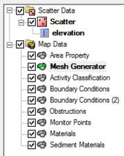
Coverages are managed using the Project Explorer. When SMS is first launched, a default coverage exists. If feature objects are created, they are placed in the current coverage. When multiple coverages are created, one coverage is designated the "active" coverage. New feature objects are always added to the active coverage and only objects in the active coverage can be edited. The figure below shows several coverages in the Project Explorer. The active coverage is displayed with a green colored icon ![]() and bold text. A coverage is made the active coverage by selecting it from the Project Explorer. In some cases it is useful to hide some or all of the coverages. The visibility of a coverage is controlled using the check box next to the coverage in the Project Explorer. In the example below, several design options are not displayed.
and bold text. A coverage is made the active coverage by selecting it from the Project Explorer. In some cases it is useful to hide some or all of the coverages. The visibility of a coverage is controlled using the check box next to the coverage in the Project Explorer. In the example below, several design options are not displayed.
Creating a New Coverage
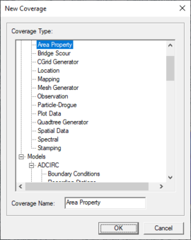
A new coverage can be created by right-clicking on the "![]() Map Data" folder in the Project Explorer. Select New Coverage from the pop-up menu. The New Coverage dialog will appear and the coverage type will need to be defined. Each coverage type is organized according to whether it is a Generic or a Model type coverage. If a coverage type was selected that has attributes associated with it, they can be changed by clicking the Attributes button. If there are no attributes associated with the selected coverage type the Attributes button will be unavailable. The name of the coverage is also specified here. After clicking the OK button, the new coverage will appear in the Project Explorer.
Map Data" folder in the Project Explorer. Select New Coverage from the pop-up menu. The New Coverage dialog will appear and the coverage type will need to be defined. Each coverage type is organized according to whether it is a Generic or a Model type coverage. If a coverage type was selected that has attributes associated with it, they can be changed by clicking the Attributes button. If there are no attributes associated with the selected coverage type the Attributes button will be unavailable. The name of the coverage is also specified here. After clicking the OK button, the new coverage will appear in the Project Explorer.
- Note: Apostrophes and other special characters are not allowed and may cause an error if included in the coverage name.
Coverage Right-Click Menu
Right-clicking on a coverage brings up a menu with the following options:
- Delete – Removes the selected coverage along with any data in the coverage.
- Duplicate – Will create a copy of the coverage.
- Rename – Allows the coverage to be given a different name. Note that apostrophes and other special characters are not allowed and may cause an error if included in the coverage name.
- Convert – Coverage feature object data can be mapped to other geometric objects or numerical models by selecting one of the Map → ... commands in the Convert submenu.
- Coordinate Conversion – The Coordinate Conversion dialog opens, which aspecifies a coordinate conversion to be performed on the coverage data.
- Metadata – Metadata associated with this coverage can be edited and viewed.
- Zoom to Coverage – Frames the graphics window to the extents of the data displayed in the selected coverage.
- Type – Sub-menu containing options to set the coverage type.
- Properties – Opens a Coverage Properties dialog that show information such as number of feature objects and the coverage's projection.
See the Map Project Explorer for more details.
Merging Existing Coverages
Occasionally, its desirable to hve independent features of two separate coverages combined into one converage. SMS allows merging these two coverages together. Select one of the coverages listed in the data tree then multi-select the other coverages to be merged. This can be done one at a time by holding the CTRL key, or several adjacent coverages can be selected by holding the SHIFT key and then clicking the last adjacent dataset.
Once all datasets to be merged have been selected, access the right-click menu and chooses Merge Coverages. A dialog may appear asking if wanting to delete the coverages used to create the merged coverage.
Coverage Types
The attributes of entities on a coverages belong to a list of attributes associated with a type of coverage. For example, arcs in mesh coverages have boundary conditions compatible with the specific finite element model they are associated with, and polygons in those coverages include attributes associated with meshing and material types.
Coverages are grouped into two categories:
- Generic – coverages for generic input prepossessing, generic output postprocessing and generic model interfaces.
- Models – coverages for specific models in SMS.
Export Coverage
To export a coverage as a DMC file, complete the following:
- Right-click on a coverage in the Project Explorer and select the Export command.
- In the Export Coverage dialog, change Save as type to be "SMS model coverage (*.dmc)".
- Save the DMC file.
See the Model Coverage File article for more information.
Related Topics
SMS – Surface-water Modeling System | ||
|---|---|---|
| Modules: | 1D Grid • Cartesian Grid • Curvilinear Grid • GIS • Map • Mesh • Particle • Quadtree • Raster • Scatter • UGrid |  |
| General Models: | 3D Structure • FVCOM • Generic • PTM | |
| Coastal Models: | ADCIRC • BOUSS-2D • CGWAVE • CMS-Flow • CMS-Wave • GenCade • STWAVE • WAM | |
| Riverine/Estuarine Models: | AdH • HEC-RAS • HYDRO AS-2D • RMA2 • RMA4 • SRH-2D • TUFLOW • TUFLOW FV | |
| Aquaveo • SMS Tutorials • SMS Workflows | ||

