WMS:Pipe and Node Parameters
Overview

The GSSHA Pipe and Node Parameters dialog is accessed by selecting one or more feature arcs, going to the GSSHA Feature Arc Properties dialog, and changing the arc type to Pipe. This dialog is used for building and editing the pipes and nodes associated with Super-Links when running a GSSHA Storm and Tile drain simulation.
Help
When running a GSSHA Storm and Tile drain simulation, it is a good idea to add more than one pipe (2 nodes) between Super-Junctions. In WMS, Super-Links are represented as arcs and Super-Junctions are represented by the 2 nodes at the end of each arc. Each link may contain 1 or more pipes and 2 or more nodes. Many of the attributes between Super-Junctions and nodes between Super-Junctions overlap. In WMS, define nodes along a Super-Link (between Super-Junctions) by adding vertices along an arc. Redistribute the vertices on the arc using the Redistribute command or can manually add vertices along an arc using the Create Vertex tool. Normally, use the following steps to define storm or tile drains and their attributes in WMS:
- Create a new GSSHA storm drain coverage and define the storm or tile drain geometry using arcs.
- Define the storm or tile drain attributes for each arc (Super-Link) using the GSSHA Arc Properties dialog.

- Define the storm or tile drain attributes and pipe invert elevations for the nodes at each end of the arcs (Super-Junctions) using the GSSHA Point/Node Properties dialog.

- For each arc (Super-Link), redistribute the vertices along the arc using the redistribute vertices command and/or manually add vertices along each arc. The spacing and number of vertices on an arc define the pipes and nodes on the arc and the lengths and slopes of the pipes.
- Define the attributes of the pipes and nodes for each arc (Super-Link) by going to the GSSHA Arc Properties dialog and clicking on the Edit Pipes and Nodes button.
- From the Pipe and Node Parameters dialog, the is the option to Initialize the Pipes from the Arc Geometry. Clicking on this button creates a pipe for each arc segment on the selected arc and creates a node for each node or vertex on the arc. Attributes associated with the Super-Link (arc) and Super-Junctions (arc nodes) are transferred to the generated pipes and nodes, but these transferred data values can be edited. Node ground surface elevations are extracted from the 2D grid elevations at the location of each node or vertex on the selected arc. These pipes and nodes are written to the GSSHA Storm Pipe Network (*.spn) file when the GSSHA project is written. It is important to define pipe and node parameters for all the pipe arcs in the storm or tile drain network. Deleting the pipes will delete the pipes and nodes from the arc, but re-initialize the pipes from the arc geometry after making any changes that need to be made or WMS may not write the correct pipe and node attributes for the selected arc.
Refer to the GSSHA Subsurface Tile and Storm Drain tutorial for more information about how to setup a storm or tile drain model.
Tools for Editing GSSHA Storm and Tile Drain Data
WMS 10.0 and later versions have several specialized tools for editing storm and tile drain data. These tools are described in this section.
Varied node distribution on an arc
The distribution of vertices (nodes) along an arc (superlink) in the GSSHA Storm Drain coverage is important in the storm/tile drain model used by GSSHA. Space nodes closely near junctions and farther apart toward the center of the superlink. WMS has an option under the Redistribute option for feature arcs that allows for defining a second bias. Each of the bias values defines the ratio of spacing between vertices at the center of the arc and at the middle of the arc. Use the same bias value along with a specified vertex spacing or a number of vertex segments to define vertices close together at the ends and far apart at the center of the superlink. See the images below.
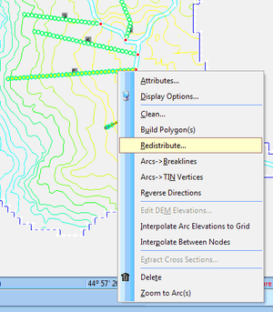
Redistribute menu command
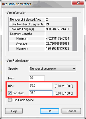
Redistribute bias options
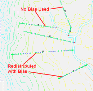
Effect of the bias option


GSSHA Storm Drain coverage
In WMS 10.0 and later, Pipe arc types are no longer defined in a GSSHA coverage. They are defined in a GSSHA Storm Drain coverage so pipes drawn inside of WMS do not impact stream elevations in the GSSHA coverage.
- File:GsshaStormDrainCoverageFig1.pngThe GSSHA Storm Drain coverage has been separated from the GSSHA Coverage
If there is an existing GSSHA project with pipe arcs in a GSSHA coverage, WMS converts these arcs to generic arcs in the GSSHA coverage and copies the pipes into a GSSHA Storm Drain coverage. This transition should work seamlessly, without needing to do any work. Existing files with a GSSHA storm drain coverage can be read and should be able to be re-written and run in GSSHA from the WMS interface. It may be desirable to delete the generic arcs that were pipes and are left in the GSSHA coverage, or leave them there. WMS does not put up any messages when converting a file from the single coverage to the GSSHA and GSSHA Storm Drain coverage model.
Auto-Updates of Pipes and Nodes and Attributes
WMS 10.0 and later versions automatically update the pipes and nodes for a superlink when a vertex is added or deleted along an arc. When redistributing vertices on an arc, WMS updates the pipes and nodes on the arc. The attributes for the new pipes and nodes are assigned based on the attributes assigned to the arc and the upstream superjunction point before adding vertices to the arc.
Elevation Interpolation Tools
WMS 10.0 and later versions have an Interpolate Between Nodes option when right-clicking on arcs. With this command, define an elevation at one or both of the nodes at the ends of the arc and then select this command. This command uses linear interpolation to assign the vertex elevations between the nodes at the ends of the arc. WMS also has a Smooth Stream/Pipe Arcs menu command that allows selecting points along a single arc and use linear interpolation between to assign elevations between the points. See the images below.


Storm/Tile Drain Adverse Slope Detection
If a segment on the arc has an adverse slope and the option to display adverse slopes is turned on, WMS displays the adverse slope in red. If any of the stream or pipe arcs in a GSSHA model have adverse slopes, the following error message is displayed when running the Model Check command under the GSSHA menu:
WARNING: The following pipe arc IDs have adverse slopes: <arc number>. It is recommended that to turn on adverse slopes in the WMS display options and correct any adverse slopes.
Then turn on adverse slopes in the display options and correct any adverse slopes. See the images below:


Editing Pipe and Node Parameters for Multiple Arcs
WMS 10.0 and later versions have a combo box at the top of the Pipe and Node Parameters dialog that allows displaying only the current arc, selected arcs, or all arcs. If the Current arc option is selected, only the pipes and nodes for the current arc are displayed, and so on. If wanting to re-initialize all the pipes and nodes from the arc geometry, select the option to show All arcs and select the Initialize Pipes from Arc Geometry button. This will re-initialize all the pipes and nodes for all the arcs in the current GSSHA Storm Drain coverage. Note that there’s also an option to only do this for the selected arcs. If wanting all the attributes for the displayed arcs to be the same, set the value in the top cell of the dialog. There is a small square in the lower right section of the cell. Double-click on this small square and the attribute will be copied to all the other pipes or nodes that are displayed. The superlink number is displayed at the top of each set of superlink attributes.

Identify Nodes with Surface Inlets
WMS 10.0 and later versions have an option in the WMS Display Options that allows displaying a special symbol for any nodes or superjunctions in the GSSHA Storm Drain coverage that have more than zero inlets.

Enhanced Hydrograph Output Options
WMS 10.0 and later versions have a Hydrograph output option for superjunctions as well as for each of the nodes in a superlink. GSSHA hydrographs are displayed at node/vertex locations instead of at grid cell centers since WMS reads the hydrographs based on link/node, pipe/node, or superjunction numbers. See the images below:


Related Topics
WMS – Watershed Modeling System | ||
|---|---|---|
| Modules: | Terrain Data • Drainage • Map • Hydrologic Modeling • River • GIS • 2D Grid • 2D Scatter |  |
| Models: | CE-QUAL-W2 • GSSHA • HEC-1 • HEC-HMS • HEC-RAS • HSPF • MODRAT • NSS • OC Hydrograph • OC Rational • Rational • River Tools • Storm Drain • SMPDBK • SWMM • TR-20 • TR-55 | |
| Toolbars: | Modules • Macros • Units • Digitize • Static Tools • Dynamic Tools • Drawing • Get Data Tools | |
| Aquaveo | ||