SMS:WAM Grid Options
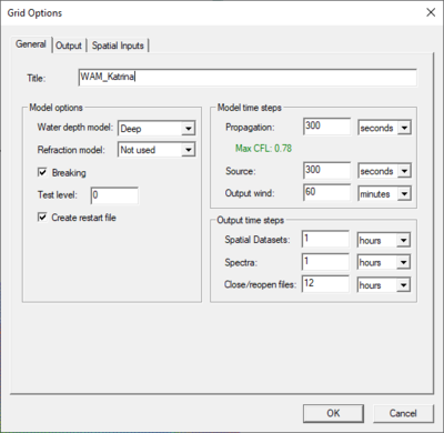
The Grid Options dialog is accessed by right-clicking on the grid entry in the Project Explorer and selecting Options. The Grid Options dialog contains the following three tabs:
General Tab
The General tab allows setting parameters for the WAM model run.
Model options
- Water depth model – Choosing a shallow depth model specifies the use of the full dispersion equation. Dispersion equation is where w is radial frequency, g is acceleration due to gravity, k is the wave number, and h is the water depth. Computes all phase and group celerity where there is depth dependence.
- Refraction model – If running in deep water, specify "Not used." It is not recommend to use if grid resolution is greater than 3-min (0.05 deg) on a spherical grid.
- Breaking – It is recommended that breaking be used when the water depth model is "Shallow." This will implement limited breaking within the WAM model.
- Test level – A control for output diagnostics and is mostly used for model debugging. The WAM model includes the capability to simulate refraction of waves caused by interaction with the ocean bottom and interaction with currents. WAM can also simulate wave breaking and create a restart file to continue analysis at a future time. The default value is "0.0", which is the minimal diagnostic output level.
- Create restart file – Causes WAM to create a restart file to continue analysis at a future time.
Model time steps
- Propagation – The Propagation time step is controlled by the Courant–Friedrichs–Lewy (CFL) condition. The CFL condition requires that the numerical solution cannot move faster than the group speed of the waves. It is recommended that the other model time steps and output time steps be multiples of the propagation time step.
- Max CFL – The CFL criteria must be less than 1.0 for WAM to run successfully. The estimated CFL value is shown below the time step. SMS computes the maximum CFL value based on the propagation time step, cell size, refraction model, and the water depth model. The value shows in green if the settings meet the criteria, or in red if they do not. Currently, the CFL estimation in SMS does not account for currents, but this is used within WAM. Therefore, the CFL estimate may show green in SMS but fail when running WAM. If this occurs, further reduce the propagation time step or change some of the other options before rerunning WAM. All of the parameters are interconnected.
- Source – This is the time step for the source term integration time step. Increasing this value can greatly decrease run times. However, it should be used with caution. It is recommended that the source term time step be no greater than 10 times the propagation time step. WAM interpolates between these intervals to attain a smaller forcing time step.
- Output wind – This time step controls how frequently the WAM simulation updates the forcing terms. WAM interpolates between these intervals to attain a smaller forcing time step.
Output Time Steps
- Spatial Datasets – This is the frequency of output that will be generated that can be loaded into SMS as datasets. The WAM file it creates is the "integrated parameter map file."
- Spectra – This is the frequency of output for spectra data at defined observation cells.
- Close/Reopen files – When writing files on a computer, often data being written is stored temporarily in RAM before being written to disk. If a file is in this state and WAM crashes, the final data may not be complete. Closing and reopening the output files forces the file system to complete writing the data to file.
Output Tab
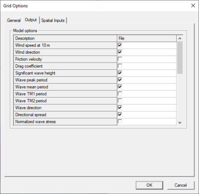
The Output tab consists of different Model options. Selecting each option will determine the dataset generated in the solution. Options include:
|
|
|
Sea waves and swell waves are defined as:
- Sea waves: waves generated by the wind blowing at the time, and in the recent past, in the area of observation.
- Swell waves: waves which have traveled into the area of observation after having been generated by previous winds in other areas. These waves may travel thousands of kilometers from their origin before dying away. There may be swell present even if the wind is calm and there are no 'sea' waves.
Spatial Inputs Tab
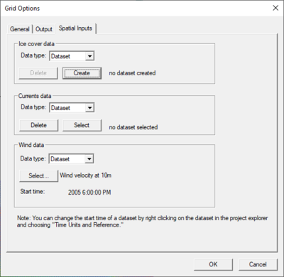
WAM uses spatial input for ice cover, currents, and wind. The Spatial Inputs section of the WAM Model Control is used to manage these datasets.
Ice Cover
The ice cover dataset is an editable scalar dataset.
- "Dataset" – After creating the dataset using the Editable Datasets dialog accessed from the Model Control, the dataset will be displayed in the project explorer in a folder named Editable Datasets. Only one ice cover dataset may exist at a time.
- "File" – Rather than using a dataset, specify the file name for ice.
Currents
The currents dataset is specified to be any vector dataset on the current grid.
- "Dataset" – The dataset and time step must both be selected. The selection may be removed by clicking on the Clear button. This deselects the dataset as the specified currents dataset, but it does not remove the dataset from the SMS project.
- "File" – Rather than using a dataset, specify the file name for currents.
Wind
The winds dataset can be set to any vector dataset that belongs to the current grid or another grid whose angle is zero and whose extents cover the current grid.
- "Dataset" – Nested grids may use the wind dataset of the parent grid. The time steps in the dataset used must match those used with the WAM simulation.
- "File" – PBL can be used to create an input wind file for WAM by selecting "WAM input" in the PBL Model Control. The fort.12 file created by PBL may be selected as the wind data. Note: This option is only useful if there is access to the "Planetary Boundary Layer" model which isn't available through SMS.
Related Topics
SMS – Surface-water Modeling System | ||
|---|---|---|
| Modules: | 1D Grid • Cartesian Grid • Curvilinear Grid • GIS • Map • Mesh • Particle • Quadtree • Raster • Scatter • UGrid |  |
| General Models: | 3D Structure • FVCOM • Generic • PTM | |
| Coastal Models: | ADCIRC • BOUSS-2D • CGWAVE • CMS-Flow • CMS-Wave • GenCade • STWAVE • WAM | |
| Riverine/Estuarine Models: | AdH • HEC-RAS • HYDRO AS-2D • RMA2 • RMA4 • SRH-2D • TUFLOW • TUFLOW FV | |
| Aquaveo • SMS Tutorials • SMS Workflows | ||


