Template:3D UGrid from Rasters Tool: Difference between revisions
No edit summary |
No edit summary |
||
| (7 intermediate revisions by 3 users not shown) | |||
| Line 1: | Line 1: | ||
===3D UGrid from Rasters=== | ===3D UGrid from Rasters=== | ||
The ''3D UGrid from Rasters'' tool is used to create a [[Unstructured_Grid#Types_of_UGrids|3D UGrid]] from multiple [[GMS:Rasters|rasters]] and a [[Unstructured_Grid#Types_of_UGrids|2D UGrid]] by extruding the 2D UGrid and creating layers inbetween the rasters using the [[GMS:Horizons|horizons]] approach. The resulting UGrid will be "stacked", meaning, there is no vertical sub-discretization of layers and the horizontal discretization of all layers is the same. Thus, no layers | The ''3D UGrid from Rasters'' tool is used to create a [[Unstructured_Grid#Types_of_UGrids|3D UGrid]] from multiple [[GMS:Rasters|rasters]] and a [[Unstructured_Grid#Types_of_UGrids|2D UGrid]] by extruding the 2D UGrid and creating layers inbetween the rasters using the [[GMS:Horizons|horizons]] approach. The resulting UGrid will be "stacked", meaning, there is no vertical sub-discretization of layers and the horizontal discretization of all layers is the same. Thus, no layers pinch out, but may have zero thickness. | ||
====Input parameters==== | ====Input parameters==== | ||
*''2D UGrid'' – The input 2D UGrid that will be used. | *''2D UGrid'' – The input 2D UGrid that will be used. | ||
*''Rasters'' – A table of rasters and their properties. | *''Rasters'' – A table of rasters and their properties. | ||
**''Horizon'' – The [[GMS:Horizons|horizon]] number. Horizons are | **''Horizon'' – The [[GMS:Horizons|horizon]] number. Horizons are numbered consecutively in the order that the strata are “deposited” (from the bottom up). | ||
**''Fill'' – If checked, | **''Fill'' – If checked, one or more layers will be created between the raster and the one below. | ||
**''Clip'' – If checked, all rasters below | **''Clip'' – If checked, all rasters below will not be permitted to go above the raster. | ||
**''Sublayers'' – Number of layers to create between the raster and the | **''Sublayers'' – Number of layers to create between the raster and the one below. Default is 1. | ||
**''Proportions'' – Sublayer proportions as a space delimited list of integers, size of Sublayers, where 1 is the base thickness. For example "1 1 2" indicates three sublayers with the first two being the same thickness and the third being twice as thick as the first. If blank, sublayers (if any) will be evenly proportioned. | **''Proportions'' – Sublayer proportions as a space delimited list of integers, size of Sublayers, where 1 is the base thickness. For example "1 1 2" indicates three sublayers with the first two being the same thickness and the third being twice as thick as the first. If blank, sublayers (if any) will be evenly proportioned. | ||
*''Target location'' – Whether to calculate elevations at the UGrid cell tops and bottoms or at the points. For MODFLOW models, "Cell tops and bottoms" is appropriate | *''Target location'' – Whether to calculate elevations at the UGrid cell tops and bottoms or at the points. For MODFLOW models, "Cell tops and bottoms" is appropriate. For HydroGeoSphere, "Points". | ||
*''Minimum layer thickness'' – The minimum thickness every layer must have. If necessary, points are moved down to satisfy this criteria, except for the top sheet of points. | *''Minimum layer thickness'' – The minimum thickness every layer must have. If necessary, points are moved down to satisfy this criteria, except for the top sheet of points. | ||
*''3D UGrid name'' – Name of the 3D UGrid that will be created. | |||
====Output parameters==== | ====Output parameters==== | ||
* | *The output is a 3D UGrid. | ||
====Current location in Toolbox==== | ====Current location in Toolbox==== | ||
| Line 22: | Line 21: | ||
====Examples==== | ====Examples==== | ||
Files for example 1 can be downloaded [https://s3.amazonaws.com/gmstutorials.aquaveo.com/2d_ugrid_from_3d_ugrid_ex1.zip here]. | |||
=====Example 1===== | |||
The following figure shows a 3D UGrid with three layers in oblique view. | |||
:[[File:raster_catalog4.png|none|frame|Raster surfaces.]] | :[[File:raster_catalog4.png|none|frame|Raster surfaces.]] | ||
The above figure shows a slice through raster surfaces that have been indexed with horizon IDs. Below we see the resulting stratigraphy if the ''Clip'' field is off (zero) for each raster. | |||
Below we see the resulting stratigraphy if the ''Clip'' field is off for each raster. | |||
:[[File:raster_catalog3.png|none|frame|Stratigraphy with the Clip field turned off.]] | :[[File:raster_catalog3.png|none|frame|Stratigraphy with the Clip field turned off.]] | ||
The next two examples show how the stratigraphy changes when the ''Clip'' field is turned on. | |||
:[[File:raster_catalog1.png |none|frame |Stratigraphy with the Clip field on for horizon 4.]] | :[[File:raster_catalog1.png |none|frame |Stratigraphy with the Clip field on for horizon 4.]] | ||
:[[File:raster_catalog2.png |none|frame |Stratigraphy with the Clip field on for horizon 3.]] | |||
The final example shows a case where the ''Fill'' field is off and the ''Clip'' field is on. | |||
:[[File:raster_catalog5.png |none|frame |Stratigraphy with the Fill-off and Clip-on for horizon 3.]] | :[[File:raster_catalog5.png |none|frame |Stratigraphy with the Fill-off and Clip-on for horizon 3.]] | ||
| Line 44: | Line 44: | ||
*[[Extrude_UGrid_Tool|Extrude UGrid Tool]] | *[[Extrude_UGrid_Tool|Extrude UGrid Tool]] | ||
[[Category:Tools]] | |||
Revision as of 16:42, 14 August 2023
3D UGrid from Rasters
The 3D UGrid from Rasters tool is used to create a 3D UGrid from multiple rasters and a 2D UGrid by extruding the 2D UGrid and creating layers inbetween the rasters using the horizons approach. The resulting UGrid will be "stacked", meaning, there is no vertical sub-discretization of layers and the horizontal discretization of all layers is the same. Thus, no layers pinch out, but may have zero thickness.
Input parameters
- 2D UGrid – The input 2D UGrid that will be used.
- Rasters – A table of rasters and their properties.
- Horizon – The horizon number. Horizons are numbered consecutively in the order that the strata are “deposited” (from the bottom up).
- Fill – If checked, one or more layers will be created between the raster and the one below.
- Clip – If checked, all rasters below will not be permitted to go above the raster.
- Sublayers – Number of layers to create between the raster and the one below. Default is 1.
- Proportions – Sublayer proportions as a space delimited list of integers, size of Sublayers, where 1 is the base thickness. For example "1 1 2" indicates three sublayers with the first two being the same thickness and the third being twice as thick as the first. If blank, sublayers (if any) will be evenly proportioned.
- Target location – Whether to calculate elevations at the UGrid cell tops and bottoms or at the points. For MODFLOW models, "Cell tops and bottoms" is appropriate. For HydroGeoSphere, "Points".
- Minimum layer thickness – The minimum thickness every layer must have. If necessary, points are moved down to satisfy this criteria, except for the top sheet of points.
- 3D UGrid name – Name of the 3D UGrid that will be created.
Output parameters
- The output is a 3D UGrid.
Current location in Toolbox
Unstructured Grids/3D UGrid from Rasters
Examples
Files for example 1 can be downloaded here.
Example 1
The following figure shows a 3D UGrid with three layers in oblique view.
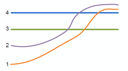 Raster surfaces.

The above figure shows a slice through raster surfaces that have been indexed with horizon IDs. Below we see the resulting stratigraphy if the Clip field is off (zero) for each raster.
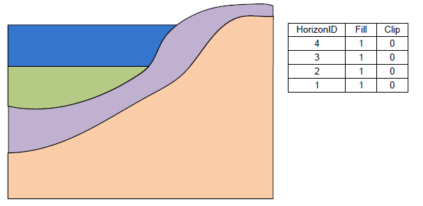 Stratigraphy with the Clip field turned off.

The next two examples show how the stratigraphy changes when the Clip field is turned on.
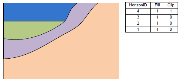 Stratigraphy with the Clip field on for horizon 4.
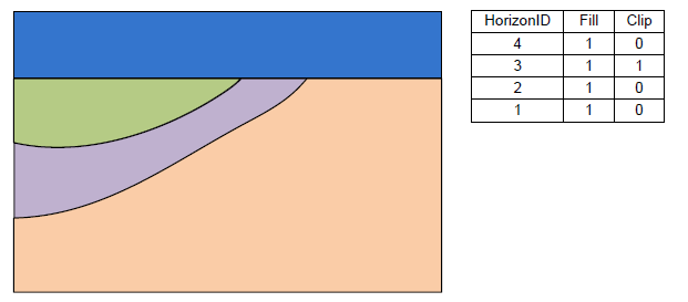 Stratigraphy with the Clip field on for horizon 3.


The final example shows a case where the Fill field is off and the Clip field is on.
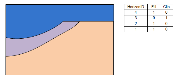 Stratigraphy with the Fill-off and Clip-on for horizon 3.
