SMS:1D Hyd Cross Section Coverage: Difference between revisions
No edit summary |
|||
| Line 10: | Line 10: | ||
; Add Arcs to Mesh : Adds all cross section arcs to an existing mesh. | ; Add Arcs to Mesh : Adds all cross section arcs to an existing mesh. | ||
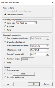
; Extract cross sections : Brings up the [[SMS:1D Hyd Cross Section Coverage#Extracting Cross Sections|''Extract Cross Sections'']] dialog where a cross section database can be created from the cross sections in the coverage. | ; Extract cross sections : Brings up the [[SMS:1D Hyd Cross Section Coverage#Extracting Cross Sections|''Extract Cross Sections'']] dialog where a cross section database can be created from the cross sections in the coverage. | ||
; Summary table : Brings up the [[SMS: | ; Summary table : Brings up the [[SMS:1D_Hyd_Cross_Section_Coverage#Summary_Table|''Summary Table Options'']] dialog which allows viewing calculations along cross section arcs. | ||
==Extracting Cross Sections== | ==Extracting Cross Sections== | ||
Revision as of 17:48, 13 July 2016
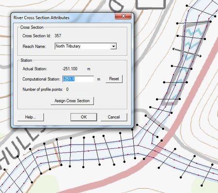
The 1D-Hydraulic Cross Section coverage is used to identify the cross section stations in the hydraulic model, and can also be used to automatically cut a cross section from an underlying digital terrain model. The attributes of a cross section feature arc is the cross section itself, along with the other parameters that define its topology in the model and include: a cross section ID (internally assigned), the reach name (inherited from the centerline arc it intersects), the station (inherited from the centerline), and any specific model attributes. The 1D-Hydraulic coverage is used in conjunction with the cross sections and digital terrain model in order to determine the thalweg position (from the centerline arc) and the left and right bank points (from the bank arcs).
A cross section is assigned automatically when cutting the cross sections, or can be assigned manually (imported from a file or entered directly) using the cross section editor.
See the help for Editing Cross Sections to learn more about how cross sections are managed and edited.
Coverage Specific Right-Click Commands
The 1D Hyd Cross Section Coverage contains all the standard commands in its right-click menu. The coverage also contains a couple specific commands unique to its right-click menu. These commands include:
- Add Arcs to Mesh
- Adds all cross section arcs to an existing mesh.
- Extract cross sections
- Brings up the Extract Cross Sections dialog where a cross section database can be created from the cross sections in the coverage.
- Summary table
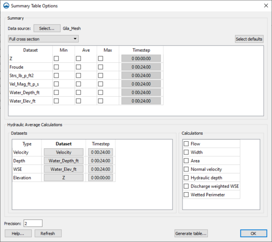
- Brings up the Summary Table Options dialog which allows viewing calculations along cross section arcs.
Extracting Cross Sections
The Extract Cross sections command uses the cross section arcs and a digital terrain model (TINs are the only source that can currently be used) to extract the elevations at vertices of the feature arc cross sections, or at the intersection points with the triangles.
Cross sections for individual arcs may be extracted by selecting the arc(s) before choosing the Extract Cross Sections command. If not cross sections are selected then the Use All Cross Sections option is used.
Point properties (thalweg, left bank, right bank) can be defined from a 1D-Hydraulic Centerline coverage, or by AutoMark. The AutoMark option will examine the elevations of the extracted cross sections and try to infer the thalweg (low point) and the left and right bank points (change of slope) automatically.
Line properties can be determined from an area property coverage by intersecting the cross section arcs with the area property polygons and marking them in the cross section database.
Cross Section Database
When extracting the cross sections, a prompt will appear asking for the name of a cross section database file. SMS stores all of the cross section information in a text database file. The cross section database can also be edited independently using the Cross Section Editor tools. Extracting cross sections with feature arcs is only way to generate cross section information, they also can be imported from spreadsheet files (cut and paste), or entered manually.
Summary Table
The summary table is a tool that allows viewing calculations along cross section arcs in a project. To use the summary table, there must exist a cross section coverage, centerline coverage, and geometry (i.e. grid, mesh, scatter). To access the summary table, right-click on the 1D-Hydraulic Cross Section coverage and select Summary Table....
Summary Table Options
The Summary Table Options dialog is where which desired calculations are specified, as well as which geometry to use, and which portions of the cross section should be used.
Data Source
The Data source Select button brings up a Select Tree Item dialog. This dialog is used to select the geometry that has the datasets for the calculations.
Cross section options
There are three options for the cross sections: "Full cross section", "Main channel only", and "Overbanks and main channel".
- "Full cross section" – This option is used when there is no cross-section database, overbanks have not been specified, or if the calculations should be done over the entire cross-section.
- "Main channel only" – This option can only be used if there is a cross-section database. The calculations will be performed only on the main channel portion of the cross section , defined as the space between the right and left overbanks.
- "Overbanks and main channel" – This option can only be used if there is a cross-section database. The calculations will be performed on three separate portions of the cross section: the left overbank, main channel, and right overbank.
Datasets
After selecting a data source, the spreadsheet will be populated with all of the scalar datasets that belong to the data source. For each dataset, toggle on minimum, average, and maximum to be calculated, as well as select the dataset time step to be used. To calculated the minimum, maximum, and average values for each cross section, SMS will interpolate the values from the dataset to the points along the cross section. These interpolated values will then be used to determine the minimum, maximum, and average value.
Defaults
The Select defaults button will search for common dataset keywords in the list and automatically turn on the average calculation. The keywords are: "water_elev", "wse", "vel_mag", "vmag", and "froude".
Advanced Calculations
Some other helpful calculations are available in the Advanced Calculations section.
- Flow – To calculate the flow over the cross sections, it is necessary to specify a velocity dataset (vector) and a depth dataset (scalar). SMS will then calculate the flow over the cross section at the specified time step.
- Width – To calculate the width of the cross sections, it is necessary to specify an elevation dataset and a water surface elevation dataset. SMS then compares the water surface elevation with the cross section elevation to determine the width.
Summary Table
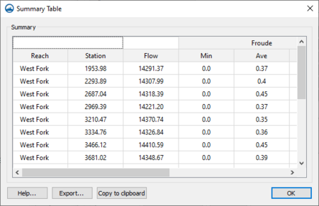
Once all of the options are set, click on Generate table... to have SMS compute the desired values and display them in a table.
Editing Cross Sections
For the new 1D Hydraulic Cross Section coverage, the cross section geometry is stored in text database file on disk. When extracting cross sections they are saved to a new (or existing) database file. However, extraction of cross sections from digital terrain models is not the only way that they can be created, nor is extraction always the only thing that needs to be done. For example other ways cross sections can be entered for use include: including importing from a spreadsheet, or entering manually. In such cases, and many times after extraction from a digital terrain model there are edits that must be performed in order to prepare the cross sections for hydraulic modeling.
Edit cross sections in one of three ways:
- When double-clicking on an arc in a 1D Hydraulic Cross Section coverage, it's possible to assign a cross section from a database. After assigning the cross section, also enter the editor for that cross section.
- Opening a cross section database for editing (or create a new database) using the Manage Cross Sections command.
- Opening an existing cross section database using the File | Open command.
The operations described in the following paragraphs can be done using the cross section editor shown in the figure below.
General Properties
In order to identify information about the cross section in the database a name (not required), a reach, a station, and the name of the topographic data used to extract the cross section (if applicable) can be defined. A note about the cross section can also be defined. Not all of these attributes are critical for the development of a hydraulic model, but they are useful in managing the cross section within a database.
Editing Geometry
Cross section points can be added, or values edited when the Geom Edit tab of the editor is active. XY values are available when the actual 3D position of each point on the cross section is known. The more traditional D-Z pairs define the distance from the starting point and a corresponding elevation.
Geo-Referencing
Geo-referencing information provides the spatial (x-y) location of the cross section and included geometry. This information is inherent in the 3D coordinates, when extracting cross sections from a digital terrain model. However, if the cross section geometry is taken from a survey then the actual x-y-z coordinates of the points may not be known. In order to use the data within SMS for flood plain delineation, a proper geo-reference must be provided.
A cross section can have one of the following georeferencing definitions: All points specified (i.e. extracted cross sections will be of this type), Use two points (i.e. the coordinates of the beginning and ending location along the cross section defined), Use one point an angle (i.e. the centerline location is known and some angle relative to it defined), or no geo-referencing defined.
The geo-referencing is defined from the Geo Ref tab in the cross section editor.
Line Properties
Line properties define segments of material properties along the cross section. When using an area property coverage during extraction from a digital terrain model these properties are automatically marked and defined. However, they can also be established manually from within the Line Props tab in the cross section editor. To manually define the properties, use the "Insert Breakpoint" tool to specify the beginning and end locations on the cross section plot for each property. These locations and values can be edited in the Line Props spreadsheet.
Point Properties
Point properties include thalweg, left bank, and right bank (other properties can be defined but are not mapped/saved to hydraulic models from within WMS) locations. When using a centerline and bank line arcs from a 1D Hydraulic Centerline coverage during extraction these points are marked. SMS can "Auto Mark" these points by looking for the lowest elevation (thalweg), and appropriate breaks in elevation/slope (banks). Point properties are edited from within the Point Props tab in the cross section editor.
Merging
It is possible to combine a surveyed cross section with a section extracted from a terrain model for the flood plain (i.e. the terrain model does not contain enough detail to define the cross section of the river) using the tools in the Merge tab in the cross section editor. Two different cross sections can be merged, with rules for locations and precedence defined in order to create a new cross section.
Filtering
It may be that there are more points defining the cross section than are necessary (or that the hydraulic model is capable of processing). The Filter tab in the cross section editor allows specifying rules for filtering "insignificant" points along the cross section. This can be particularly important when extracting cross sections from a dense digital terrain model.
Managing Cross Sections
For the new 1D Hydraulic Cross Section coverage, the cross section geometry is stored in text database file on disk. When extracting cross sections they are saved to a new (or existing) database file. This database was the basis for the development of the cross section data in the ArcHydro data model. Cross sections in the database can be used for the development of hydraulic models such as HEC-RAS.
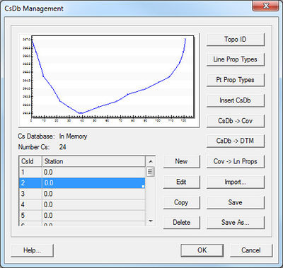
The Manage Cross Sections command allows creating a new database or opening an existing database to add geometries, edit existing ones, and provide proper geo-referencing information. It is also possible to open a cross section database using the Open command from the File menu.
Cross Section Database Definition
When setting up a new database the following attributes can be defined:
- Topo ID – A topographic identifier and description that identifies where the cross section database was derived from. Create a new Topo ID for each database.
- Line Prop Types – By default SMS uses only a Material ID, but other properties could be defined for general use (they will not immediately be used by supported hydraulic models).
- Point Prop Types – By default SMS uses thalweg, left bank, and right bank but other point properties could be defined for general use.
The Cross Section Database Management dialog also allows creating a new cross section; edit, copy, or delete an existing cross section; insert an entire database (merge databases together); convert a cross section database to a coverage (the georeferencing of cross sections must be provided for the cross section to be included in the coverage); create a digital terrain model from the cross section geometry; and converting the coverage to line properties.
Related Topics
SMS – Surface-water Modeling System | ||
|---|---|---|
| Modules: | 1D Grid • Cartesian Grid • Curvilinear Grid • GIS • Map • Mesh • Particle • Quadtree • Raster • Scatter • UGrid |  |
| General Models: | 3D Structure • FVCOM • Generic • PTM | |
| Coastal Models: | ADCIRC • BOUSS-2D • CGWAVE • CMS-Flow • CMS-Wave • GenCade • STWAVE • WAM | |
| Riverine/Estuarine Models: | AdH • HEC-RAS • HYDRO AS-2D • RMA2 • RMA4 • SRH-2D • TUFLOW • TUFLOW FV | |
| Aquaveo • SMS Tutorials • SMS Workflows | ||
