User:Jcreer/SMS:AdH Interface
AdH Coverages
The AdH interface includes a few map coverages. These map coverages are used to provide input for the AdH simulation. AdH use the following model specific coverages:
- Boundary Conditions
- Materials
- Sediment Materials
AdH Boundary Conditions
Arc Attributes
Flux Output
Sediment Diversion
Arc Transport Constituents
Transport Constituents
AdH Materials
AdH Sediment Materials
AdH Simulation
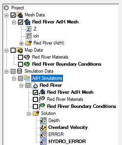
Simulations are available for AdH starting in SMS 13.3. A simulation should contain a 2D mesh and an AdH boundary conditions coverage, and optional AdH coverages. Right-clicking on the simulation will display options and dialogs.
To create a new simulation:
- Right-click on empty space in the Project Explorer and select New Simulation | AdH. A new tree item
 will appear.
 - Drag and drop simulation components under the newly created simulation tree item
 . Components available include:
- 2D mesh
- Boundary Conditions coverage
- Materials coverage
Multiple AdH simulations can be included in a single project.
Simulation Components
An AdH simulation uses the following components in the model run:
- 2D mesh – Any generic 2D mesh will work. Generally this mesh should be created from the Mesh Generation coverage.
- Boundary Conditions coverage – Contains arcs defining the boundary condition attributes for the model run.
- Materials coverage – Allows creating recording stations at specified nodal locations.
- Sediment Material coverage –
Each component can be added to the simulation by selecting the component and dragging it under the simulation item ![]() in the Project Explorer. Linked 2D mesh
in the Project Explorer. Linked 2D mesh ![]() and coverages
and coverages ![]() will be displayed under the simulation.
will be displayed under the simulation.
Linking Components
After a simulation has been created, components may be added to the simulation. Components are usually added by clicking on the component item in the Project Explorer and dragging the item under the ADCIRC simulation. A link (![]() or
or ![]() ) is then created between the component and the simulation.
) is then created between the component and the simulation.
Components can also be added to a simulation by right-clicking on the component in the project explorer and selecting the simulation name in the Apply To submenu. The Apply To submenu becomes available once a simulation has been created.
Components can be removed by right-clicking on the component link under the simulation and select Remove.
If a component is updated, it must be reapplied to the simulation.
AdH Model Control
Time
Iteration
Operation
Output
Constants
Hot Start
Advanced
SMS – Surface-water Modeling System | ||
|---|---|---|
| Modules: | 1D Grid • Cartesian Grid • Curvilinear Grid • GIS • Map • Mesh • Particle • Quadtree • Raster • Scatter • UGrid |  |
| General Models: | 3D Structure • FVCOM • Generic • PTM | |
| Coastal Models: | ADCIRC • BOUSS-2D • CGWAVE • CMS-Flow • CMS-Wave • GenCade • STWAVE • WAM | |
| Riverine/Estuarine Models: | AdH • HEC-RAS • HYDRO AS-2D • RMA2 • RMA4 • SRH-2D • TUFLOW • TUFLOW FV | |
| Aquaveo • SMS Tutorials • SMS Workflows | ||
