User:Jcreer/SMS:EWN: Difference between revisions
| (121 intermediate revisions by 2 users not shown) | |||
| Line 6: | Line 6: | ||
===EWN Polygon Properties Dialog=== | ===EWN Polygon Properties Dialog=== | ||
[[File:EWN Polygon Prop.png|thumb|400 px|The ''EWN Polygon Properties'' dialog]] | [[File:EWN Polygon Prop.png|thumb|400 px|The ''EWN Polygon Properties'' dialog]] | ||
Access the ''EWN Polygon Properties'' dialog by right-clicking | Access the ''EWN Polygon Properties'' dialog by right-clicking on a polygon in an EWN Features coverage and selecting the '''Assign EWN Features...''' command. The dialog has the following options: | ||
*''Name'' | *''Name'' – This allows assigning a name to the polygon. | ||
*''Classification'' | *''Classification'' – If the polygon represents one of the EWN types, it can provide an N value (roughness) both here and when generating a dataset. The available classification types in the combo box include the following: | ||
**"Unassigned" | **"Unassigned" | ||
**"Mesh Transition Zone" | **"Mesh Transition Zone" | ||
| Line 18: | Line 18: | ||
**"West Coast Beach/Dune" | **"West Coast Beach/Dune" | ||
**"Gulf Coast Beach/Dune" | **"Gulf Coast Beach/Dune" | ||
*''Insert Feature'' | *''Insert Feature'' – This must be checked for this feature to be included in processing. | ||
*''Manning's N'' | *''Manning's N'' | ||
*''Elevation'' | *''Elevation'' – The available elevation types include the following: | ||
*''Slope'' | **"Constant" – This is the default. It allows for creation of an entity at fixed elevation (i.e. -0.5 for half a meter below MSL). | ||
*''Maximum Slope Distance'' | **"Z-Offset" – This allows for creation of an entity with elevation offset from the current mesh. | ||
*''Maximum Transition Distance'' | *''Specify slope'' – Allows specifying data for the slope. Note: In ADCIRC, there is often an instability if the cell size is too small. Specifying a slope can result in small cells around the polygon. Caution is recommended when using this. | ||
*''Metadata'' | **''Slope (Rise/Run (ft))'' – This is usually smaller than 0.1. | ||
*''Preview'' | **''Maximum Slope Distance (ft)'' | ||
**'''Select UGrid/Mesh''' | *''Maximum Transition Distance'' – This defines the maximum range of influence. It can be viewed in the preview window. The combo box allows picking what the entered value represents: | ||
**''Element area change limit'' | **"Bounding box factor" – This is a positive number that SMS uses to create a bounding box around the polygon. It is expanded on all four sides by a percentage of the box size (1.0 results in a transition zone 3 times wider and taller than the polygon bounding box). | ||
**'''Generate mesh with | **"Specified distance (ft)" – Specify a distance to transition from object into background mesh. (Not recommended) | ||
**''Add new mesh to SMS on exit'' | **"Transition polygon" – Define a polygon defining the transition region. (Not recommended) | ||
*''Metadata'' – This allows entering information about the classification guide. | |||
*''Preview'' | |||
**'''Select UGrid/Mesh...''' – Select the background mesh that this object is being inserted into. | |||
**''Element area change limit (fast 0.0 ↔ 1.0 slow)'' – Select a transition change limit (0.0-1.0). A smaller value will allow for faster transitions, but worse element quality. The recommendation is to keep this at 0.5 or higher. This will not allow the transition to go beyond the "maximum" specified in the Maximum Transition Distance. | |||
**'''Generate mesh with feature...''' | |||
**''Add new mesh to SMS on exit'' – If there is only one feature, or wanting to process features one at a time, use this option. | |||
==Sediment Volume Management Coverage== | ==Sediment Volume Management Coverage== | ||
[[File:EWN SedimentVolumeManagement.png|thumb|375 px|The feature object ''Sediment Volume Management''dialog]] | [[File:EWN SedimentVolumeManagement.png|thumb|375 px|The feature object ''Sediment Volume Management''dialog]] | ||
The Sediment Volume Management coverage allows calculating cut and fill for sediment volume. The coverage allows assigning sediment attributes to polygons and also provides a tool to perform sediment volume calculations. | The Sediment Volume Management coverage allows for calculating cut and fill for sediment volume. The coverage allows for assigning sediment attributes to polygons and also provides a tool to perform sediment volume calculations. The coverage needs to be set to the Sediment Volume Management type. | ||
===Sediment Volume Management Polygon Attributes=== | ===Sediment Volume Management Polygon Attributes=== | ||
The ''Sediment Volume Management'' dialog for polygon attributes can be | The ''Sediment Volume Management'' dialog for polygon attributes can be reached by right-clicking on a selected polygon and selecting the '''Sediment Properties...''' command. The dialog contains the following properties: | ||
*Name | *''Name'' – This allows for a name to be entered. | ||
*Type | *''Type'' – This allows the type to be specified, including the following options: | ||
**None | **"None" | ||
**Specified cut region | **"Specified cut region" | ||
**Specified fill region | **"Specified fill region" | ||
**Available cut region | **"Available cut region" | ||
**Available fill region | **"Available fill region" | ||
*Cut/fill option | *''Cut/fill option'' – When enabled, this allows the cut/fill option to be specified, including the following options: | ||
**Constant elevation | **"Constant elevation" | ||
**Relative thickness | **"Relative thickness" | ||
**Total volume by elevation | **"Total volume by elevation" | ||
**Total volume by thickness | **"Total volume by thickness" | ||
*Value | *''Value'' – This allows a value to be specified. | ||
*Priority | *''Priority'' – This represents the priority. | ||
*Priority value | *''Priority value'' – This represents the priority value. | ||
===Sediment Volume Management Tool=== | ===Sediment Volume Management Tool=== | ||
[[File:EWN SedimentVolumeManagementTool.png|thumb|500 px|The ''Sediment Volume Management'' tool]] | [[File:EWN SedimentVolumeManagementTool.png|thumb|500 px|The ''Sediment Volume Management'' tool]] | ||
The ''Sediment Volume Management'' tool dialog is reached by right-clicking on the sediment volume management coverage and selecting the | The ''Sediment Volume Management'' tool dialog is reached by right-clicking on the sediment volume management coverage and selecting the '''Sediment Volume Management...''' command. There must already be at least one Sediment Volume Management Polygon Attribute created for the dialog to appear. The dialog has the following options, split into the sections they are found in: | ||
''Input'' | ''Input'' | ||
*Source geometry | *'''Source geometry Select...''' – This will bring up the ''Select EWN Geometry'' dialog, where the source geometry can be selected for use. | ||
*Maximum slope | *''Maximum slope'' – This allows a maximum slope to be specified. | ||
''Computations'' | ''Computations (volume units in ft^3)'' | ||
* | *''Computation table'' – A region that contains a list of all the attributes and their data, some of which can be altered within the table. It has columns for the following data, which are gathered from what was entered for Sediment Volume Management Polygon Attributes: | ||
*Compute | **''ID'' – This is the ID that was assigned for the region. | ||
*Save to File | **''Name'' – This is the name that was entered for the region. | ||
*Sum of cut | **''Type'' – This is the type that was specified for the region. | ||
*Net of cut | **''Priority'' – This is the priority that was assigned for the region. | ||
*Sum of fill | **''Priority%'' – This is the the priority value that was assigned for the region. | ||
*Net of | **''Cut/Fill Type'' – This is the Cut/Fill type that was assigned for the region. | ||
**''Value'' – This is the value that was assigned for the region. | |||
**''Total Volume Based on Slope'' – This is the amount of material that could be dredged/placed if the specified depth/elevation values were ignored. | |||
**''Required Volume'' – This is the volume for specified cuts/fills. | |||
**''Available Volume'' – This is the volume for available cuts/fills. | |||
**''Cut Volume'' – This is the actual amount cut from this polygon. | |||
**''Fill Volume'' – This is the actual amount placed into this polygon. | |||
*'''Sort/Normalize''' – This deals with the priority column, it will normalize the priority values for them to be accurate percentages and sort them. | |||
*'''Compute''' – This runs the Sediment Volume Management tool and updates the values in the Computation table. | |||
*'''Save to File''' – This will bring up the ''Save'' dialog, where a file can be saved of the output. | |||
*''Sum of cut'' – This allows the sum of cut to be entered. | |||
*''Net of cut'' – This allows the net of cut to be entered. | |||
*''Sum of fill'' – This allows the sum of fill to be entered. | |||
*''Net of fill'' – This allows the net of fill to be entered. | |||
Output options | ''Output options'' | ||
*New geometry name | *''New geometry name'' – This allows a name for a new geometry to be entered. | ||
*Generate new geometry on OK | *'''Generate new geometry on OK''' – Checking this will mean that a new geometry is generated when '''OK''' is selected on the dialog. | ||
{{-}} | {{-}} | ||
==Channel | ==Mesh Tools Coverage== | ||
=== | The coverage needs to be set to the Mesh Tools type. In a Mesh Tools coverage there are several tools available. These tools are found by right-clicking a Mesh Tools coverage in the Project Explorer and going to the ''Tools'' submenu. | ||
===Polygons from Features=== | |||
This tool will generate polygons from included features. An arc must be in the coverage for this. Set the features to be included by checking the box next to ''Include this feature when creating polygons'' in the ''Channel/Embankment Properties'' dialog for the feature. This will create a new ''Generated polygons'' coverage to to hold the new polygons. | |||
Do not include arcs that are connected as those will cause overlapping polygons, which will give an error and not properly generate. | |||
===Trim Coverage from Polygons=== | |||
[[File:Trim coverage properties.png|thumb|Example of the ''Trim Coverage Properties'' dialog]] | |||
After creating a polygon in the Mesh Tools coverage, this tool is used to remove everything that is not wanted inside or outside the polygon. The dialog has the following options: | |||
*'''Choose coverage to trim Select...''' – This will bring up the ''Select Feature Coverage'' dialog, where a feature coverage to trim can be selected. | |||
*''Trimming option'' – This is a drop-down that contains two options for trimming: | |||
**"Trim to inside" – Feature objects will be inside the polygon. | |||
**"Trim to outside" – Keep feature objects that are outside the polygon. | |||
*''Trimming buffer distance'' – A value can be entered for the trimming buffer distance. | |||
*''New coverage name'' – A name can be entered for the new trim coverage. | |||
{{-}} | |||
===Merge Meshes=== | |||
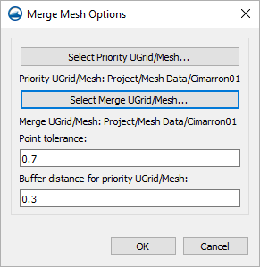
[[File:Merge mesh options.png|thumb|Example of the ''Merge Mesh Options'' dialog]] | |||
This allows merging two meshes, UGrids, or scatter sets together. The dialog has the following options: | |||
*'''Select Priority UGrid/Mesh...''' – This will bring up the ''Select UGrid/Mesh'' dialog where the priority UGrid or Mesh can be selected. | |||
*'''Select Merge UGrid/Mesh...''' – This will bring up another ''Select UGrid/Mesh'' dialog where this time the merge UGrid or Mesh can be selected. | |||
*''Point tolerance'' – A value can be entered for the point tolerance. | |||
*''Buffer distance for priority UGrid/Mesh'' – A value for the buffer distance of the priority UGrid or Mesh can be entered. | |||
{{-}} | |||
===Channel/Embankment Properties=== | ===Channel/Embankment Properties=== | ||
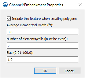
[[File:Channel embankment properties.png|thumb|Example of the ''Channel/Embankment Properties'' dialog]] | |||
The following dialog can be accessed by right-clicking a selected arc and selecting the '''Assign Properties...''' command. | |||
The dialog has the following options: | |||
*''Include this feature when creating polygons'' – This is a checkbox that when selected, will include the selected feature when creating polygons. | |||
*''Average element/cell width (ft)'' – A value can be entered for the average width of elements or cells (in feet). | |||
*''Number of elements/cells (must be even)'' – A value can be entered for the amount of elements and cells (which must be even). | |||
*''Bias (0.01-100.0)'' – A value can be entered for the bias, ranging from 0.01 to 100.0. | |||
{{-}} | |||
==Bridge-Piers Coverage== | |||
The coverage needs to be set to the Bridge-Piers type. In a Bridge-Piers coverage there are several tools available. These tools are found by right-clicking a Bridge-Piers coverage in the Project Explorer and going to the ''Tools'' submenu. | |||
===Generate Bridge Mesh=== | |||
This will bring up the ''Generate Mesh'' dialog, where there is a log where information will be output as the mesh is being generated, and any error messages output. This may not be up long enough to be read depending on how quickly the process finishes. Once this is complete, within the ''Bridge-Piers'' coverage, the geometry should reflect the new bridge mesh. | |||
<description correct?, don't bother with image?> | |||
{{-}} | |||
===Insert Bridge into Mesh=== | |||
This will bring up the ''Insert Bridge'' dialog. The dialog has the following options: | |||
*''Source geometry'' – | |||
**''' Select...''' – This will bring up the ''Select Source Geometry'' dialog, where existing source geometry can be selected for use. | |||
*''Element area change limit (fast 0.0 ↔ 1.0 slow)'' – Select a transition change limit (0.0-1.0). A smaller value will allow for faster transitions, but worse element quality. The recommendation is to keep this at 0.5 or higher. | |||
[[File:Insert-bridge.png|thumb|none|600 px|Example of the ''Insert Bridge'' dialog]] | |||
{{-}} | |||
===Generate Bridge Polygon Coverage=== | |||
This will bring up the ''Generate Mesh'' dialog, where there is a log where information will be output as the polygon coverage is being generated, and any error messages output. This may not be up long enough to be read depending on how quickly the process finishes. Once this is complete, there should be a new ''Bridge'' coverage. | |||
<description correct?, don't bother with image?> | |||
{{-}} | |||
===Bridge/Pier Properties=== | |||
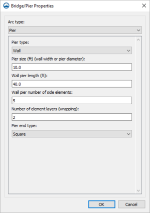
[[File:Bridge-pier-pier-wall.png|thumb|Example of the ''Bridge/Pier Properties'' dialog, set to Arc type "Pier" and Pier type "Wall"]] | |||
The ''Bridge/Pier Properties'' dialog can be accessed by right-clicking a selected arc and selecting the '''Assign Properties...''' command. | |||
As it starts out, the dialog has the following options in a drop-drown under ''Arc type'': | |||
*"Unassigned" – The default option that contains no properties or attributes. | |||
*"Bridge" – Designates the arc as a bridge structure. When "Bridge" is selected, the dialog has the following options: | |||
**''Bridge width (ft)'' – Set the width (in feet) of the bridge. | |||
**''Bridge wrapping width (ft)'' – Set the wrapping width (in feet) of the bridge. | |||
**''Insert bridge entrance/exit (pressure zone)'' – If this is checked, a bridge entrance and exit will be inserted. | |||
*"Pier" – Designates the arc as a pier structure. When this ''Arc type'' is selected, the first option, the ''Pier type'' drop-down, will determine what the rest of the options below it are. The ''Pier type'' options are: | |||
**"Wall" &nash; When "Wall" is selected as the ''Pier type'', the dialog has the following options: | |||
***''Pier size (ft) (wall width or pier diameter)'' – The size of the pier (in feet), which can be thought of as either the wall width or the pier diameter. | |||
***''Wall pier length (ft)'' – The length of the wall pier (in feet). | |||
***''Wall pier number of side elements'' – The number of side elements of the wall pier. | |||
***''Number of element layers (wrapping)'' – The number of wrapping layer elements. | |||
***''Pier end type'' – This is a drop-down where the end type can be selected from the following options: | |||
****"Square" – A squared off end to the pier. | |||
****"Rounded" – A rounded off end to the pier. | |||
****"Sharp" – A sharp end to the pier. | |||
**"Pier Group" – When "Pier group" is selected as the ''Pier type'', the dialog has the following options: | |||
***''Pier size (ft) (wall width or pier diameter)'' – The size of the pier (in feet), which can be thought of as either the wall width or the pier diameter. | |||
***''Number of element layers (wrapping)'' – The number of wrapping layer elements. | |||
***''Number of piers in group'' – The number of piers contained within the group. | |||
***''Pier group spacing (ft)'' – By how much feet the piers are spaced within the group. | |||
*"Abutment" – Designates the arc as an abutment structure. | |||
Depending on which of these are selected, the options listed below the ''Arc type'' will be different. | |||
{{-}} | |||
==EWN Classification Properties== | ==EWN Classification Properties== | ||
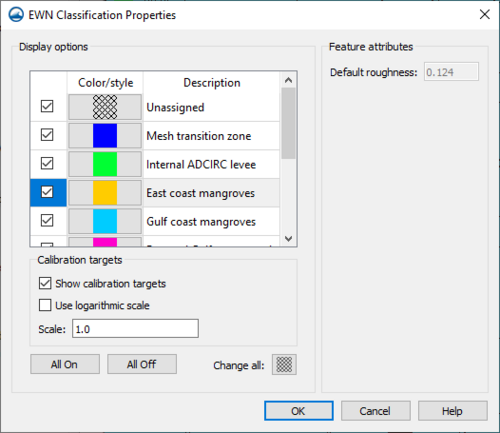
[[File:EWN Classification Properties.png|thumb | [[File:EWN Classification Properties.png|thumb|500 px|The ''EWN Classification Properties'' dialog]] | ||
The ''EWN Classification Properties'' dialog is accessed by right-clicking on the EWN Features coverage and selecting the '''EWN Classification Properties...''' command. The dialog has the following options: | |||
*''Display Options'' – This includes a list of the types from a database/data file. These are the available "polygon types" when assigning polygon attributes. Metadata for each type is displayed in the [[#EWN_Polygon_Properties_Dialog|EWN Polygon Properties]] dialog. | |||
*''Checkboxes'' – These are used to control which polygons are displayed. | |||
*''Color/style'' – This is used to adjust the display of polygons. | |||
*''All On/Off toggles'' – These can be used to select all types or deselect them all. | |||
*''Change all'' – This can be used to change all types to the same pattern (not the same color). | |||
*''Default roughness'' – This is used when generating a roughness dataset for ADCIRC. | |||
{{-}} | |||
<!--Read from a file SMS bin folder when tool is accessed(?) | |||
*binary area is D:\quick\SMS131_trunk\Dev\SMS\APP | |||
.\Python36\Lib\site-packages\xms\ewn\data\resources\EWN Table.csv--> | |||
==EWN Tools== | ==EWN Tools== | ||
The commands are available with these steps: | |||
*Create a coverage of type ''Models'' | ''Misc Tools (Beta)'' | '''EWN Features'''. | |||
*Right-click on the coverage and hover the mouse over "Tools". | |||
**'''Generate Elevation Raster...''' | |||
**'''Generate Roughness Dataset...''' | |||
**'''Insert EWN Features...''' | |||
**'''Insert ADCIRC Levees...''' | |||
===Generate Elevation Raster=== | ===Generate Elevation Raster=== | ||
Access the ''Generate Elevation Raster'' dialog by right-clicking on an EWN Features coverage and selecting the ''Tools'' | '''Generate Elevation Raster...''' command. The dialog has the following options: | |||
*'''Source geometry: Select...''' – This will bring up the ''Select Source Geometry'' dialog, where existing source geometry can be selected for use. | |||
*''Cells (w x h)'' – When a source geometry is selected, this will allow for the width and height of the raster to be specified in cells, either by entering a value or incrementing/decrementing by one. | |||
*''Cell size'' – This determines what size each cell will be. | |||
*'''Output file: Select...''' – This will bring up a ''Save'' dialog where a file can be outputted. | |||
[[File:GenerateElevationRaster.png|thumb|none|600 px|Example of the ''Generate Elevation Raster'' dialog]] | |||
{{-}} | |||
===Generate Roughness Dataset=== | ===Generate Roughness Dataset=== | ||
[[File:Generate roughness data set.png|thumb|350px|Example of the ''Generate Roughness Data Set'' dialog]] | |||
Access the ''Generate Roughness'' dialog by right-clicking on an EWN Features coverage and selecting the ''Tools'' | '''Generate Roughness Dataset...''' command. The dialog has the following options: | |||
*'''Target geometry Select...''' – This will bring up the ''Select EWN Geometry'' dialog, where the EWN geometry can be selected for use. | |||
*''Constant'' – When selected, this will allow a constant value to be set as the initial value. | |||
*''Data Set'' – When selected, this will enable a '''Select...''' button to be used to choose a Data Set. | |||
*'''Data Set Select...''' – When this is clickable, this will bring up the ''Select Initial Roughness Data Set'' dialog, which allows a specific Data Set from the Project Explorer to be selected. | |||
*'''EWN Feature coverages Select...''' – This will bring up the ''Select EWN Feature Coverages'' dialog, where an EWN Feature coverage can be selected. | |||
*''EWN Feature coverages List'' – This is a list that contains the EWN Feature coverages that have been selected for this window. | |||
*'''Move Up''' – This will move a coverage up on the list. | |||
*'''Move Down''' – This will move a coverage down on the list. | |||
*''Data set name'' – This will determine what the Roughness Data Set will be named. | |||
{{-}} | |||
===Insert EWN Features=== | ===Insert EWN Features=== | ||
[[File:Insert EWN Features.png|thumb|350 px|The ''Insert EWN Features'' dialog]] | [[File:Insert EWN Features.png|thumb|350 px|The ''Insert EWN Features'' dialog]] | ||
Access the ''Insert EWN Features'' dialog by right-clicking on an EWN Features coverage and selecting the ''Tools'' | '''Insert EWN Features...''' command. The dialog has the following options: | |||
*'''Target geometry Select...''' – This will bring up the ''Select EWN Geometry'' dialog, where the target geometry can be selected for use. | |||
*''Element area change limit (fast 0.0 ↔ 1.0 slow)'' – Select a transition change limit (0.0-1.0). A smaller value will allow for faster transitions, but worse element quality. The recommendation is to keep this at 0.5 or higher. | |||
*'''EWN Feature coverages Select...''' – This will bring up the ''Select EWN Feature Coverages'' dialog, where an EWN Feature coverage can be selected. | |||
*'''Move up''' – This will move a coverage up on the list. | |||
*'''Move down''' – This will move a coverage down on the list. | |||
*'''EWN Feature coverages List''' – This is a list that contains the EWN Feature coverages that have been selected for this window. | |||
{{-}} | {{-}} | ||
===Insert ADCIRC Levees=== | ===Insert ADCIRC Levees=== | ||
[[File:EWN Insert ADCIRC Levee.png|thumb|250 px|The ''Insert ADCIRC Levee'' dialog]] | [[File:EWN Insert ADCIRC Levee.png|thumb|250 px|The ''Insert ADCIRC Levee'' dialog]] | ||
Access the ''Insert ADCIRC Levee'' dialog by right-clicking on an EWN Features coverage and selecting the ''Tools'' | '''Insert ADCIRC Levees...''' command. The dialog has the following options: | |||
*'''Source geometry Select...''' – This will bring up the ''Select Source Geometry'' dialog, where the source geometry can be selected for use. | |||
*'''ADCIRC BC coverage Select...''' – This will bring up the ''Select ADCIRC Boundary Condition Coverage'' dialog, where the ADCIRC BC coverage can be selected for use. | |||
*''Element area change limit (fast 0.0 ↔ 1.0 slow)'' – Select a transition change limit (0.0-1.0). A smaller value will allow for faster transitions, but worse element quality. The recommendation is to keep this at 0.5 or higher. | |||
{{Navbox SMS}} | {{Navbox SMS}} | ||
[[Category:EWN]] | [[Category:EWN]] | ||
Latest revision as of 17:10, 27 April 2021
Engineering with Nature (EWN) is a tool to aid in implementing engineering features into natural environments.
EWN Features Coverage
The EWN Features coverage allows creating feature objects to represent structures.
EWN Polygon Properties Dialog
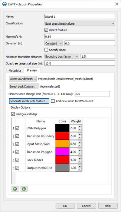
Access the EWN Polygon Properties dialog by right-clicking on a polygon in an EWN Features coverage and selecting the Assign EWN Features... command. The dialog has the following options:
- Name – This allows assigning a name to the polygon.
- Classification – If the polygon represents one of the EWN types, it can provide an N value (roughness) both here and when generating a dataset. The available classification types in the combo box include the following:
- "Unassigned"
- "Mesh Transition Zone"
- "Internal ADCIRC Levee"
- "East Coast Mangroves"
- "Gulf Coast Mangroves"
- "West Coast Marsh"
- "East Coast Beach/Dune"
- "West Coast Beach/Dune"
- "Gulf Coast Beach/Dune"
- Insert Feature – This must be checked for this feature to be included in processing.
- Manning's N
- Elevation – The available elevation types include the following:
- "Constant" – This is the default. It allows for creation of an entity at fixed elevation (i.e. -0.5 for half a meter below MSL).
- "Z-Offset" – This allows for creation of an entity with elevation offset from the current mesh.
- Specify slope – Allows specifying data for the slope. Note: In ADCIRC, there is often an instability if the cell size is too small. Specifying a slope can result in small cells around the polygon. Caution is recommended when using this.
- Slope (Rise/Run (ft)) – This is usually smaller than 0.1.
- Maximum Slope Distance (ft)
- Maximum Transition Distance – This defines the maximum range of influence. It can be viewed in the preview window. The combo box allows picking what the entered value represents:
- "Bounding box factor" – This is a positive number that SMS uses to create a bounding box around the polygon. It is expanded on all four sides by a percentage of the box size (1.0 results in a transition zone 3 times wider and taller than the polygon bounding box).
- "Specified distance (ft)" – Specify a distance to transition from object into background mesh. (Not recommended)
- "Transition polygon" – Define a polygon defining the transition region. (Not recommended)
- Metadata – This allows entering information about the classification guide.
- Preview
- Select UGrid/Mesh... – Select the background mesh that this object is being inserted into.
- Element area change limit (fast 0.0 ↔ 1.0 slow) – Select a transition change limit (0.0-1.0). A smaller value will allow for faster transitions, but worse element quality. The recommendation is to keep this at 0.5 or higher. This will not allow the transition to go beyond the "maximum" specified in the Maximum Transition Distance.
- Generate mesh with feature...
- Add new mesh to SMS on exit – If there is only one feature, or wanting to process features one at a time, use this option.
Sediment Volume Management Coverage
The Sediment Volume Management coverage allows for calculating cut and fill for sediment volume. The coverage allows for assigning sediment attributes to polygons and also provides a tool to perform sediment volume calculations. The coverage needs to be set to the Sediment Volume Management type.
Sediment Volume Management Polygon Attributes
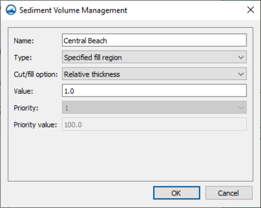
The Sediment Volume Management dialog for polygon attributes can be reached by right-clicking on a selected polygon and selecting the Sediment Properties... command. The dialog contains the following properties:
- Name – This allows for a name to be entered.
- Type – This allows the type to be specified, including the following options:
- "None"
- "Specified cut region"
- "Specified fill region"
- "Available cut region"
- "Available fill region"
- Cut/fill option – When enabled, this allows the cut/fill option to be specified, including the following options:
- "Constant elevation"
- "Relative thickness"
- "Total volume by elevation"
- "Total volume by thickness"
- Value – This allows a value to be specified.
- Priority – This represents the priority.
- Priority value – This represents the priority value.
Sediment Volume Management Tool
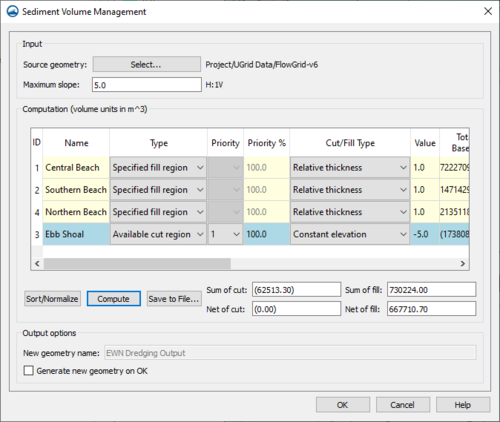
The Sediment Volume Management tool dialog is reached by right-clicking on the sediment volume management coverage and selecting the Sediment Volume Management... command. There must already be at least one Sediment Volume Management Polygon Attribute created for the dialog to appear. The dialog has the following options, split into the sections they are found in:
Input
- Source geometry Select... – This will bring up the Select EWN Geometry dialog, where the source geometry can be selected for use.
- Maximum slope – This allows a maximum slope to be specified.
Computations (volume units in ft^3)
- Computation table – A region that contains a list of all the attributes and their data, some of which can be altered within the table. It has columns for the following data, which are gathered from what was entered for Sediment Volume Management Polygon Attributes:
- ID – This is the ID that was assigned for the region.
- Name – This is the name that was entered for the region.
- Type – This is the type that was specified for the region.
- Priority – This is the priority that was assigned for the region.
- Priority% – This is the the priority value that was assigned for the region.
- Cut/Fill Type – This is the Cut/Fill type that was assigned for the region.
- Value – This is the value that was assigned for the region.
- Total Volume Based on Slope – This is the amount of material that could be dredged/placed if the specified depth/elevation values were ignored.
- Required Volume – This is the volume for specified cuts/fills.
- Available Volume – This is the volume for available cuts/fills.
- Cut Volume – This is the actual amount cut from this polygon.
- Fill Volume – This is the actual amount placed into this polygon.
- Sort/Normalize – This deals with the priority column, it will normalize the priority values for them to be accurate percentages and sort them.
- Compute – This runs the Sediment Volume Management tool and updates the values in the Computation table.
- Save to File – This will bring up the Save dialog, where a file can be saved of the output.
- Sum of cut – This allows the sum of cut to be entered.
- Net of cut – This allows the net of cut to be entered.
- Sum of fill – This allows the sum of fill to be entered.
- Net of fill – This allows the net of fill to be entered.
Output options
- New geometry name – This allows a name for a new geometry to be entered.
- Generate new geometry on OK – Checking this will mean that a new geometry is generated when OK is selected on the dialog.
Mesh Tools Coverage
The coverage needs to be set to the Mesh Tools type. In a Mesh Tools coverage there are several tools available. These tools are found by right-clicking a Mesh Tools coverage in the Project Explorer and going to the Tools submenu.
Polygons from Features
This tool will generate polygons from included features. An arc must be in the coverage for this. Set the features to be included by checking the box next to Include this feature when creating polygons in the Channel/Embankment Properties dialog for the feature. This will create a new Generated polygons coverage to to hold the new polygons.
Do not include arcs that are connected as those will cause overlapping polygons, which will give an error and not properly generate.
Trim Coverage from Polygons
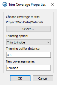
After creating a polygon in the Mesh Tools coverage, this tool is used to remove everything that is not wanted inside or outside the polygon. The dialog has the following options:
- Choose coverage to trim Select... – This will bring up the Select Feature Coverage dialog, where a feature coverage to trim can be selected.
- Trimming option – This is a drop-down that contains two options for trimming:
- "Trim to inside" – Feature objects will be inside the polygon.
- "Trim to outside" – Keep feature objects that are outside the polygon.
- Trimming buffer distance – A value can be entered for the trimming buffer distance.
- New coverage name – A name can be entered for the new trim coverage.
Merge Meshes
This allows merging two meshes, UGrids, or scatter sets together. The dialog has the following options:
- Select Priority UGrid/Mesh... – This will bring up the Select UGrid/Mesh dialog where the priority UGrid or Mesh can be selected.
- Select Merge UGrid/Mesh... – This will bring up another Select UGrid/Mesh dialog where this time the merge UGrid or Mesh can be selected.
- Point tolerance – A value can be entered for the point tolerance.
- Buffer distance for priority UGrid/Mesh – A value for the buffer distance of the priority UGrid or Mesh can be entered.
Channel/Embankment Properties
The following dialog can be accessed by right-clicking a selected arc and selecting the Assign Properties... command. The dialog has the following options:
- Include this feature when creating polygons – This is a checkbox that when selected, will include the selected feature when creating polygons.
- Average element/cell width (ft) – A value can be entered for the average width of elements or cells (in feet).
- Number of elements/cells (must be even) – A value can be entered for the amount of elements and cells (which must be even).
- Bias (0.01-100.0) – A value can be entered for the bias, ranging from 0.01 to 100.0.
Bridge-Piers Coverage
The coverage needs to be set to the Bridge-Piers type. In a Bridge-Piers coverage there are several tools available. These tools are found by right-clicking a Bridge-Piers coverage in the Project Explorer and going to the Tools submenu.
Generate Bridge Mesh
This will bring up the Generate Mesh dialog, where there is a log where information will be output as the mesh is being generated, and any error messages output. This may not be up long enough to be read depending on how quickly the process finishes. Once this is complete, within the Bridge-Piers coverage, the geometry should reflect the new bridge mesh.
<description correct?, don't bother with image?>
Insert Bridge into Mesh
This will bring up the Insert Bridge dialog. The dialog has the following options:
- Source geometry –
- Select... – This will bring up the Select Source Geometry dialog, where existing source geometry can be selected for use.
- Element area change limit (fast 0.0 ↔ 1.0 slow) – Select a transition change limit (0.0-1.0). A smaller value will allow for faster transitions, but worse element quality. The recommendation is to keep this at 0.5 or higher.
Generate Bridge Polygon Coverage
This will bring up the Generate Mesh dialog, where there is a log where information will be output as the polygon coverage is being generated, and any error messages output. This may not be up long enough to be read depending on how quickly the process finishes. Once this is complete, there should be a new Bridge coverage.
<description correct?, don't bother with image?>
Bridge/Pier Properties
The Bridge/Pier Properties dialog can be accessed by right-clicking a selected arc and selecting the Assign Properties... command. As it starts out, the dialog has the following options in a drop-drown under Arc type:
- "Unassigned" – The default option that contains no properties or attributes.
- "Bridge" – Designates the arc as a bridge structure. When "Bridge" is selected, the dialog has the following options:
- Bridge width (ft) – Set the width (in feet) of the bridge.
- Bridge wrapping width (ft) – Set the wrapping width (in feet) of the bridge.
- Insert bridge entrance/exit (pressure zone) – If this is checked, a bridge entrance and exit will be inserted.
- "Pier" – Designates the arc as a pier structure. When this Arc type is selected, the first option, the Pier type drop-down, will determine what the rest of the options below it are. The Pier type options are:
- "Wall" &nash; When "Wall" is selected as the Pier type, the dialog has the following options:
- Pier size (ft) (wall width or pier diameter) – The size of the pier (in feet), which can be thought of as either the wall width or the pier diameter.
- Wall pier length (ft) – The length of the wall pier (in feet).
- Wall pier number of side elements – The number of side elements of the wall pier.
- Number of element layers (wrapping) – The number of wrapping layer elements.
- Pier end type – This is a drop-down where the end type can be selected from the following options:
- "Square" – A squared off end to the pier.
- "Rounded" – A rounded off end to the pier.
- "Sharp" – A sharp end to the pier.
- "Pier Group" – When "Pier group" is selected as the Pier type, the dialog has the following options:
- Pier size (ft) (wall width or pier diameter) – The size of the pier (in feet), which can be thought of as either the wall width or the pier diameter.
- Number of element layers (wrapping) – The number of wrapping layer elements.
- Number of piers in group – The number of piers contained within the group.
- Pier group spacing (ft) – By how much feet the piers are spaced within the group.
- "Wall" &nash; When "Wall" is selected as the Pier type, the dialog has the following options:
- "Abutment" – Designates the arc as an abutment structure.
Depending on which of these are selected, the options listed below the Arc type will be different.
EWN Classification Properties
The EWN Classification Properties dialog is accessed by right-clicking on the EWN Features coverage and selecting the EWN Classification Properties... command. The dialog has the following options:
- Display Options – This includes a list of the types from a database/data file. These are the available "polygon types" when assigning polygon attributes. Metadata for each type is displayed in the EWN Polygon Properties dialog.
- Checkboxes – These are used to control which polygons are displayed.
- Color/style – This is used to adjust the display of polygons.
- All On/Off toggles – These can be used to select all types or deselect them all.
- Change all – This can be used to change all types to the same pattern (not the same color).
- Default roughness – This is used when generating a roughness dataset for ADCIRC.
EWN Tools
The commands are available with these steps:
- Create a coverage of type Models | Misc Tools (Beta) | EWN Features.
- Right-click on the coverage and hover the mouse over "Tools".
- Generate Elevation Raster...
- Generate Roughness Dataset...
- Insert EWN Features...
- Insert ADCIRC Levees...
Generate Elevation Raster
Access the Generate Elevation Raster dialog by right-clicking on an EWN Features coverage and selecting the Tools | Generate Elevation Raster... command. The dialog has the following options:
- Source geometry: Select... – This will bring up the Select Source Geometry dialog, where existing source geometry can be selected for use.
- Cells (w x h) – When a source geometry is selected, this will allow for the width and height of the raster to be specified in cells, either by entering a value or incrementing/decrementing by one.
- Cell size – This determines what size each cell will be.
- Output file: Select... – This will bring up a Save dialog where a file can be outputted.
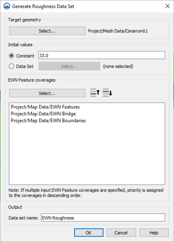
Generate Roughness Dataset
Access the Generate Roughness dialog by right-clicking on an EWN Features coverage and selecting the Tools | Generate Roughness Dataset... command. The dialog has the following options:
- Target geometry Select... – This will bring up the Select EWN Geometry dialog, where the EWN geometry can be selected for use.
- Constant – When selected, this will allow a constant value to be set as the initial value.
- Data Set – When selected, this will enable a Select... button to be used to choose a Data Set.
- Data Set Select... – When this is clickable, this will bring up the Select Initial Roughness Data Set dialog, which allows a specific Data Set from the Project Explorer to be selected.
- EWN Feature coverages Select... – This will bring up the Select EWN Feature Coverages dialog, where an EWN Feature coverage can be selected.
- EWN Feature coverages List – This is a list that contains the EWN Feature coverages that have been selected for this window.
- Move Up – This will move a coverage up on the list.
- Move Down – This will move a coverage down on the list.
- Data set name – This will determine what the Roughness Data Set will be named.
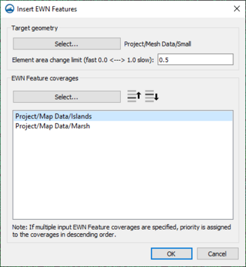
Insert EWN Features
Access the Insert EWN Features dialog by right-clicking on an EWN Features coverage and selecting the Tools | Insert EWN Features... command. The dialog has the following options:
- Target geometry Select... – This will bring up the Select EWN Geometry dialog, where the target geometry can be selected for use.
- Element area change limit (fast 0.0 ↔ 1.0 slow) – Select a transition change limit (0.0-1.0). A smaller value will allow for faster transitions, but worse element quality. The recommendation is to keep this at 0.5 or higher.
- EWN Feature coverages Select... – This will bring up the Select EWN Feature Coverages dialog, where an EWN Feature coverage can be selected.
- Move up – This will move a coverage up on the list.
- Move down – This will move a coverage down on the list.
- EWN Feature coverages List – This is a list that contains the EWN Feature coverages that have been selected for this window.
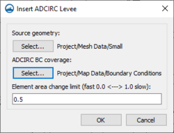
Insert ADCIRC Levees
Access the Insert ADCIRC Levee dialog by right-clicking on an EWN Features coverage and selecting the Tools | Insert ADCIRC Levees... command. The dialog has the following options:
- Source geometry Select... – This will bring up the Select Source Geometry dialog, where the source geometry can be selected for use.
- ADCIRC BC coverage Select... – This will bring up the Select ADCIRC Boundary Condition Coverage dialog, where the ADCIRC BC coverage can be selected for use.
- Element area change limit (fast 0.0 ↔ 1.0 slow) – Select a transition change limit (0.0-1.0). A smaller value will allow for faster transitions, but worse element quality. The recommendation is to keep this at 0.5 or higher.
SMS – Surface-water Modeling System | ||
|---|---|---|
| Modules: | 1D Grid • Cartesian Grid • Curvilinear Grid • GIS • Map • Mesh • Particle • Quadtree • Raster • Scatter • UGrid |  |
| General Models: | 3D Structure • FVCOM • Generic • PTM | |
| Coastal Models: | ADCIRC • BOUSS-2D • CGWAVE • CMS-Flow • CMS-Wave • GenCade • STWAVE • WAM | |
| Riverine/Estuarine Models: | AdH • HEC-RAS • HYDRO AS-2D • RMA2 • RMA4 • SRH-2D • TUFLOW • TUFLOW FV | |
| Aquaveo • SMS Tutorials • SMS Workflows | ||
