SMS:FESWMS Sediment Control
| This contains information about features no longer in use for the current release of SMS. The content may not apply to current versions. |
The FESWMS engine was modified in 2005 to include a capacity for sediment transport. In fact at this time the official name of the system changed from Flo2DH to FST2DH. The "ST" stands for "Sediment Transport". That functionality is supported in the SMS interface for the model. Shortly after the capability was added to the numerical engine, a study was performed at Brigham Young University to verify the capabilities and provide sample applications. It was discovered that the FESWMS engine does indeed provide reasonable estimates of sediment transport, including scour and deposition patterns for some applications of non-cohesive sediments. However, the study also revealed that several of the advertised capabilities do not function, and the model is prone to numerical instablities. We advise caution and patience for modelers attempting to use this capability of the FESWMS engine.
Before simulating sediment transport, set up a non-transport project. Then add the sediment tranpsport parameters and attributes. This is done in three main steps:
- Set the model parameters
- Define the bed conditions and sediment grain sizes
- Define the sediment boundary conditions
Model Parameters
A sediment transport simulation requires several settings in the General tab of the FESWMS Model Control be set. These include the Run Type, the FST2DH Output and the Solution Type. Set the Run Type to Sediment or Semi-coupled. The "Sediment option uses an existing hydrodynamic solution. The Semi-coupled option instructs the engine to switch back and forth between hydrodynamic calculations and sediment calculations at each time step. Tests have shown that for stability, the Semi-coupled option should be used. The "Solution Type" should be set to "Dynamic". The Sediment Transport Solutions toggle should also be turned on.
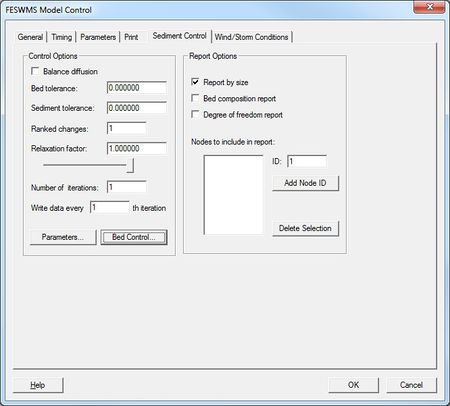
The Sediment Transport tab of the FESWMS Model Control provides access to the other parameters related to sediment transport calculations in FESWMS. The Report Options section allows specification of what information will be saved to the report (*.prt) file by FESWMS. The Control Options section of the sediment control allows for specification of the numeric properties such as convergence criteria an maximum iterations the engine should use while solving the sediment transport quantities. This section also includes two buttons to acces the sediment parameters and the bed definition options.
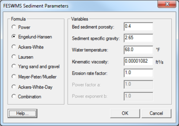
The parameters include a choice of eight transport formulae. Each formula requires associated variables to be specified.
Bed Conditions
FST2DH performs sediment calculations using a three layer system. The first layer is the "Active bed-layer". This is the layer where deposition and scour can occur. The scour at a single time step is limited to the thickness of the active layer. The second layer consists of material deposited on top of the native bed. If core samples have been taken and show a variation in particle distributions, a depositional-layer may be defined. The third layer defines the native bed. Total scour is limited to the depth or thickness of this layer.
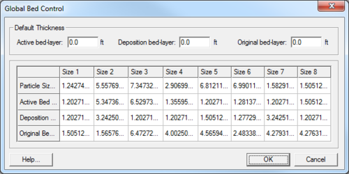
The Bed Control button in the sediment control options allows accessing the interface to define the global bed. This include the thickness of the three computation layers and the distribution of particle sizes in each of those layers. FST2DH supports up to 8 particle sizes. Define the characteristic particle size for each gradation and the percent that gradation makes of each of the three layers. If a single size gradation is specified, the three percentages would all be 100%.
The global bed definitions apply to the entire domain unless a local specification is made. This is done by selecting the nodes in the area the local definition changes and selecting Local Parameters in the FESWMS menu.
Limitation
Tests have shown that numerical sensitivity increases as the number of particle sizes increases. Use as few as possible to represent the situation. Sensitivity also increases with long duration runs (over 1 week).
Sediment Boundary Conditions
Sediment boundary conditions must be applied at all open boundaries just as hydraulic conditions must be defined at those locations. In the case of sediment, specify the amount of sediment entering the domain over that open boundary using one of the following options:
- Don't specify inflow sediment. This means clear water is entering the domain.
- Specify volume of material per time as an essential or natural boundary condition for each particle size.
- Specify concentration (ppm) as an essential or natural condition for each particle size.
- Allow FST2DH to compute the inflow sediments assuming equilibrium conditions.
Limitation
Tests have shown that only the clear water and equilibrium condition boundary conditions produce reasonable results.
Related Topics
| [hide] SMS – Surface-water Modeling System | ||
|---|---|---|
| Modules: | 1D Grid • Cartesian Grid • Curvilinear Grid • GIS • Map • Mesh • Particle • Quadtree • Raster • Scatter • UGrid |  |
| General Models: | 3D Structure • FVCOM • Generic • PTM | |
| Coastal Models: | ADCIRC • BOUSS-2D • CGWAVE • CMS-Flow • CMS-Wave • GenCade • STWAVE • WAM | |
| Riverine/Estuarine Models: | AdH • HEC-RAS • HYDRO AS-2D • RMA2 • RMA4 • SRH-2D • TUFLOW • TUFLOW FV | |
| Aquaveo • SMS Tutorials • SMS Workflows | ||


