SMS:STWAVE Model Control: Difference between revisions
No edit summary |
|||
| (47 intermediate revisions by the same user not shown) | |||
| Line 1: | Line 1: | ||
The Model Control… command in the [[SMS:STWAVE Menu|STWAVE | [[File:STWAVE MC Parameters.png|thumb|400 px|STWAVE ''Model Control'' dialog showing the ''Parameters'' tab.]] | ||
The '''Model Control…'''command in the [[SMS:STWAVE Menu|STWAVE simulation menu]] opens the STWAVE ''Model Control'' dialog. This dialog is divided into multiple tabs with different options. | |||
== | ==Parameters== | ||
* ''STWAVE plane mode'' – Determines how wave transformation and generation will be computed. | |||
* | ** "Full Plane" – Allows wave transformation and generation on the full 360 degree plane. Consult the STWAVE model documentation for more information. | ||
* Number of | ** "Half Plane" – Allows wave energy to propagate only from teh offshore towards the nearshore. Consult the STWAVE model documentation for more information. | ||
* | * ''Source Terms'' – Specifies whether STWAVE should generate waves using wind and the input spectrum or whether to use the wave spectrum. | ||
* | *''Depth'' – Determines the depth type used in the simulation run. | ||
**"Nontransient" – Default option. | |||
**"Transient" – Allows selecting a transient depth dataset for spatial varied depth. | |||
**"Coupled" – Indicates that using a coupled simulation for the depth type. | |||
* ''Current Interaction'' – Specifies whether currents will be used as input to the model. | |||
* ''Bottom Friction'' – Specifies which friction type is to be used, if any. | |||
**"JONSWAP constant" – Uses a constant for the bottom friction value using the JONSWAP formulation. | |||
**"JONSWAP dataset" – Allows selecting a dataset containing the bottom friction value using the JONSWAP formulation. | |||
**"Manning constant" – Uses a constant for the bottom friction value using a Manning's n formulation. | |||
**"Manning dataset" – Allows selecting a dataset containing the bottom friction value using a Manning's n formulation. | |||
* ''Surge Fields'' – Specifies whether surge fields are being used, or a constant tidal offset. | |||
* ''Wind Fields'' – Specifies whether wind fields (spatially varied wind) are being used, or a constant wind magnitude and direction. | |||
* ''Ice Fields'' – Specifies whether an ice dataset is being used. This is a scalar dataset that defines the percent of ice in each grid cell. | |||
:* ''Ice Threshold'' – If an ice dataset is being used, this value is needed to specify to threshold concentration level. Any cells with a percentage of ice higher than this threshold will be considered inactive by STWAVE. | |||
*''Number of grid partitions (processing)'' – Used for parallel simulations. | |||
**''I'' – Number of partitions in the I-direction. | |||
**''J'' – Number of partitions in the J-direction. | |||
== | == Boundary Control == | ||
[[File:STWAVE MC Boundary.png|thumb|400 px|STWAVE ''Model Control'' dialog showing the ''Boundary control'' tab.]] | |||
* '' | The boundary condition for STWAVE consists of one or more energy spectra entering on one or more open edges of the grid. Traditionally, specify a single spectra that is assigned to all of the cells on the offshore edge. In this situation specify one spectra for each wave case or time snap being simulated. Alternately, the input spectra can be interpolated to the cells on the offshore edge(s) from a parent STWAVE or WAM grid. | ||
* | *''Source'' – Select the source for the external boundary conditions. | ||
* '' | ** "Spectral coverage" – Uses the spectral coverage in the simulation for all boundary conditions. | ||
* '' | ** "None" – Requires that energy spectra be entered. | ||
* ''' | *''Interpolation'' – Selects the interpolation method to use for the grid boundary. | ||
* ''' | **"None (single point)" – Applies a single input spectrum along the entire grid boundary. | ||
* ''' | **"Linear" – Used to apply multiple input spectrum along the entire grid boundary using the linear interpolation method. | ||
* ''' | **"Morphic" – Used to apply multiple input spectrum along the entire grid boundary using the morphic interpolation method. | ||
* '''Use | *Computational spectral grid | ||
* '''Number | **Number | ||
* ''' | **Delta | ||
**Minimum | |||
**Maximum | |||
*Subset | |||
*''Sides'' – Specified when using a spectral coverage source. The types of boundary conditions include: | |||
** "Specified spectrum" – This may come from a parent grid if using nesting. Otherwise, a button to the right will be used to assign the spectral coverage to the boundary. | |||
** "1D transformed spectrum" – This boundary type allows energy to propagate along the boundary without interference. The cells would have the same energy if the grid was extended and the boundary became interior to a larger grid. | |||
** "Zero spectrum" – The boundary doesn't have any spectral energy applied. | |||
*''Case data'' – Defines the time step or cases that will be used and the input boundary conditions for each. | |||
**''Wind direction angle convention'' – Controls allow choosing the convention that will be used for the wind direction field in the events spreadsheet. Options include: "Cartesian", "Meteorologic", "Oceanographic", and "Shore normal". | |||
**''Time'' – The time offset value representing how much later the time is than the specified reference time. Hence, if 5 is entered for the time offset, and the time units is hours, then it is the case of 5 hours later. When nesting is used, the case ids, and the number of cases, will be determined by the parent simulation. | |||
**''Wind Direction'' – Available if "Constant value" has been selected on the ''Parameters" tab. | |||
**''Wind Magnitude'' – Available if "Constant value" has been selected on the ''Parameters" tab. | |||
**''Water Level'' – Available if "Constant value" has been selected on the ''Parameters" tab. | |||
==Output Control== | |||
[[File:STWAVE MC OutputControl.png|thumb|400 px|STWAVE ''Model Control'' dialog showing the ''Output Control'' tab]] | |||
The ''STWAVE Output Control'' dialog is used to specify the solutions files STWAVE should output. | |||
The following datasets are always written: | |||
* '''Height''' | |||
* '''Period''' | |||
* '''Direction''' | |||
* '''Wave Vector''' (magnitude of height with wave direction) | |||
* '''1/fma''' – Period that represents the inverse of the spectral peak frequency redefined for local wind growth cases | |||
The options include: | |||
* ''Radiation stresses'' – If this is on, radiation stresses will be calculated and output into datasets | |||
* ''C2Shore'' | |||
* ''Output stations'' | |||
**''Use output stations'' | |||
* ''Breaking'' – This will output a dataset representing the wave breaking. For full-plane, this can be no indices (off) or write indices which gives a value of 1 where breaking occurs and 0.0 otherwise. Half-plane has the full-plane options and has an additional option to calculate energy dissipation; this will give a dataset of energy dissipation. | |||
==Interations Control== | |||
[[File:STWAVE MC IterationsControl.png|thumb|300 px|STWAVE ''Model Control'' dialog showing the ''Iterations Control'' tab.]] | |||
The STWAVE ''Iterations Control'' dialog is reached through the ''STWAVE Model Control'' dialog. Here the number, stop value, and stop percent of iterations can be set. The tab contains the following options: | |||
:''Iterations Parameters'' – Used for full-plane simulations. | |||
:* ''Maximum number of initial iterations'' – Number to perform per snap IDD. | |||
:* ''Initial iteration stop value'' – The initial iteration stopping convergence criteria. | |||
:* ''Initial iteration stop percent'' – The initial iteration stopping percentage criteria. | |||
:* ''Maximum number of final iterations''– Number to perform per snap IDD. | |||
:* ''Final iteration stop value'' – The final iteration stopping convergence criteria. | |||
:* ''Final iteration stop percent'' – The final iteration stopping percentage criteria. | |||
==Related Topics== | ==Related Topics== | ||
[[SMS:STWAVE Menu|STWAVE Menu]] | [[SMS:STWAVE Menu|STWAVE Menu]] | ||
[[Category:STWAVE]] | {{Template:Navbox SMS}} | ||
[[Category:STWAVE|M]] | |||
[[Category:STWAVE Dialogs|mod]] | |||
[[Category:SMS Model Control|S]] | |||
Latest revision as of 21:15, 20 November 2018
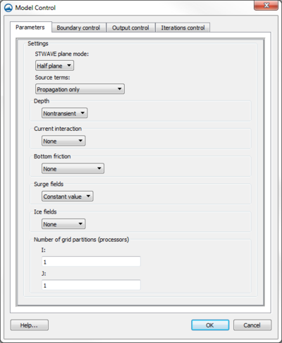
The Model Control…command in the STWAVE simulation menu opens the STWAVE Model Control dialog. This dialog is divided into multiple tabs with different options.
Parameters
- STWAVE plane mode – Determines how wave transformation and generation will be computed.
- "Full Plane" – Allows wave transformation and generation on the full 360 degree plane. Consult the STWAVE model documentation for more information.
- "Half Plane" – Allows wave energy to propagate only from teh offshore towards the nearshore. Consult the STWAVE model documentation for more information.
- Source Terms – Specifies whether STWAVE should generate waves using wind and the input spectrum or whether to use the wave spectrum.
- Depth – Determines the depth type used in the simulation run.
- "Nontransient" – Default option.
- "Transient" – Allows selecting a transient depth dataset for spatial varied depth.
- "Coupled" – Indicates that using a coupled simulation for the depth type.
- Current Interaction – Specifies whether currents will be used as input to the model.
- Bottom Friction – Specifies which friction type is to be used, if any.
- "JONSWAP constant" – Uses a constant for the bottom friction value using the JONSWAP formulation.
- "JONSWAP dataset" – Allows selecting a dataset containing the bottom friction value using the JONSWAP formulation.
- "Manning constant" – Uses a constant for the bottom friction value using a Manning's n formulation.
- "Manning dataset" – Allows selecting a dataset containing the bottom friction value using a Manning's n formulation.
- Surge Fields – Specifies whether surge fields are being used, or a constant tidal offset.
- Wind Fields – Specifies whether wind fields (spatially varied wind) are being used, or a constant wind magnitude and direction.
- Ice Fields – Specifies whether an ice dataset is being used. This is a scalar dataset that defines the percent of ice in each grid cell.
- Ice Threshold – If an ice dataset is being used, this value is needed to specify to threshold concentration level. Any cells with a percentage of ice higher than this threshold will be considered inactive by STWAVE.
- Number of grid partitions (processing) – Used for parallel simulations.
- I – Number of partitions in the I-direction.
- J – Number of partitions in the J-direction.
Boundary Control
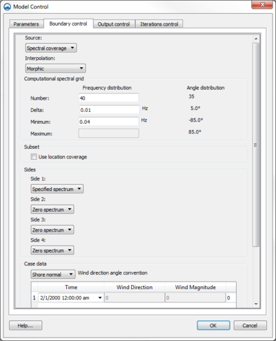
The boundary condition for STWAVE consists of one or more energy spectra entering on one or more open edges of the grid. Traditionally, specify a single spectra that is assigned to all of the cells on the offshore edge. In this situation specify one spectra for each wave case or time snap being simulated. Alternately, the input spectra can be interpolated to the cells on the offshore edge(s) from a parent STWAVE or WAM grid.
- Source – Select the source for the external boundary conditions.
- "Spectral coverage" – Uses the spectral coverage in the simulation for all boundary conditions.
- "None" – Requires that energy spectra be entered.
- Interpolation – Selects the interpolation method to use for the grid boundary.
- "None (single point)" – Applies a single input spectrum along the entire grid boundary.
- "Linear" – Used to apply multiple input spectrum along the entire grid boundary using the linear interpolation method.
- "Morphic" – Used to apply multiple input spectrum along the entire grid boundary using the morphic interpolation method.
- Computational spectral grid
- Number
- Delta
- Minimum
- Maximum
- Subset
- Sides – Specified when using a spectral coverage source. The types of boundary conditions include:
- "Specified spectrum" – This may come from a parent grid if using nesting. Otherwise, a button to the right will be used to assign the spectral coverage to the boundary.
- "1D transformed spectrum" – This boundary type allows energy to propagate along the boundary without interference. The cells would have the same energy if the grid was extended and the boundary became interior to a larger grid.
- "Zero spectrum" – The boundary doesn't have any spectral energy applied.
- Case data – Defines the time step or cases that will be used and the input boundary conditions for each.
- Wind direction angle convention – Controls allow choosing the convention that will be used for the wind direction field in the events spreadsheet. Options include: "Cartesian", "Meteorologic", "Oceanographic", and "Shore normal".
- Time – The time offset value representing how much later the time is than the specified reference time. Hence, if 5 is entered for the time offset, and the time units is hours, then it is the case of 5 hours later. When nesting is used, the case ids, and the number of cases, will be determined by the parent simulation.
- Wind Direction – Available if "Constant value" has been selected on the Parameters" tab.
- Wind Magnitude – Available if "Constant value" has been selected on the Parameters" tab.
- Water Level – Available if "Constant value" has been selected on the Parameters" tab.
Output Control
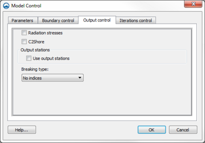
The STWAVE Output Control dialog is used to specify the solutions files STWAVE should output.
The following datasets are always written:
- Height
- Period
- Direction
- Wave Vector (magnitude of height with wave direction)
- 1/fma – Period that represents the inverse of the spectral peak frequency redefined for local wind growth cases
The options include:
- Radiation stresses – If this is on, radiation stresses will be calculated and output into datasets
- C2Shore
- Output stations
- Use output stations
- Breaking – This will output a dataset representing the wave breaking. For full-plane, this can be no indices (off) or write indices which gives a value of 1 where breaking occurs and 0.0 otherwise. Half-plane has the full-plane options and has an additional option to calculate energy dissipation; this will give a dataset of energy dissipation.
Interations Control
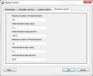
The STWAVE Iterations Control dialog is reached through the STWAVE Model Control dialog. Here the number, stop value, and stop percent of iterations can be set. The tab contains the following options:
- Iterations Parameters – Used for full-plane simulations.
- Maximum number of initial iterations – Number to perform per snap IDD.
- Initial iteration stop value – The initial iteration stopping convergence criteria.
- Initial iteration stop percent – The initial iteration stopping percentage criteria.
- Maximum number of final iterations– Number to perform per snap IDD.
- Final iteration stop value – The final iteration stopping convergence criteria.
- Final iteration stop percent – The final iteration stopping percentage criteria.
Related Topics
SMS – Surface-water Modeling System | ||
|---|---|---|
| Modules: | 1D Grid • Cartesian Grid • Curvilinear Grid • GIS • Map • Mesh • Particle • Quadtree • Raster • Scatter • UGrid |  |
| General Models: | 3D Structure • FVCOM • Generic • PTM | |
| Coastal Models: | ADCIRC • BOUSS-2D • CGWAVE • CMS-Flow • CMS-Wave • GenCade • STWAVE • WAM | |
| Riverine/Estuarine Models: | AdH • HEC-RAS • HYDRO AS-2D • RMA2 • RMA4 • SRH-2D • TUFLOW • TUFLOW FV | |
| Aquaveo • SMS Tutorials • SMS Workflows | ||


