SMS:Arcs
SMS has many utilities that can be used to modify feature arcs. Most of these can be accessed by selecting and right-clicking on the arcs that are to be operated on.
Delete
This command deletes the selected arcs. SMS will prompt to confirm that the deletion is desired if the Confirm Deletions option is enabled in the SMS Preferences.
Show Observation Plot
This command is a shortcut to create an observation plot for the selected arc(s). The plot will use the selected arcs and generate a curve for the active dataset in the active mesh if one exists. If a mesh does not exist the plot will use the active dataset in the active scatter set if that exists.
Split Feature Arc
Arcs are used to represent features in a conceptual model. A feature arc may represent a very small (short) individual feature, or it may represent a convoluted complex feature such as an entire shoreline. Two sample applications include arcs representing a shoreline, or arcs representing the thalweg of a river. There are advantages to having a single arc represent a long feature. These include the ability to select the entire feature easily, it is less cumbersome to manage the feature because there are less features, and to ensure that there are no gaps in the feature because it is a single arc. However, there are also applications and purposes for splitting the arc into pieces. One such example is illustrated by the change of shape an arc undergoes when it is redistributed. The vertices move, but the feature nodes do not. In this situation, making key points nodes prevents the arcs shape from loosing its ability to represent these key locations. In the case of a thalweg, it could be advantageous to have a separate arc for each section of the river. Each arc would then span from one river station to another (perhaps every 100 yards or meters, or each river mile).
This utility is in the right-click menu when selecting one or more arcs. The command brings up the Split Arcs Tool dialog. In this dialog provide criterion for splitting the selected arc(s) into multiple arcs. If desiring to process all the arcs in a coverage, use Select All first.
There dialog includes three toggle boxes associated with criteria including:
- Split long arcs – If this is selected, specify a length (labeled as ft or m) based on the current projection. Processed arcs will be split into arcs of this specified length starting at the first of the arc. The last arc in the group will generally not be the specified length.
- Split sharp corners – If this is selected, specify an angle (labeled as degrees). This is the angle of deviation from one arc segment to the next. A straight line has an angle of deviation of 0.0. If the arc doubled back on itself completely, the angle of deviation is 180 degrees. This deviation is a magnitude. A left turn is processed identically to a right turn. Processed arcs will be split at vertices where the arc direction changes more than the specified angle.
- Split long segments – If this is selected, specify a threshold length. If a segment is longer than this threshold, the vertices at either end will be converted to nodes making it a separate arc.
If multiple toggles are selected, the arc will first be split based on maximum arc length, the resulting arcs will be split based on angle, and finally the resulting arcs will be processed for long segments. This will retain the feature of creating feature nodes at the key length locations, and then add additional feature nodes at bends.
Offset Arc

The offset arc command (arc right-click) provides a mechanism to create additional arcs in a coverage by offsetting from the selected arc(s). Multiple offsets can be created in a single command. This command brings up a dialog that asks for a number of parameters including:
- The direction of the offset (to the left of the arc, to the right of the arc or both).
- The number of arcs to create in the specified direction.
- The maximum offset in the specified direction. If more than one offset is created on a side, the offset provided is for the last offset and the others are interpolated between the original arc and the specified offset. (If to arcs are created on the left side with an offset of 10.0, the first is offset by 5 and the second is offset by 10.)
This command uses the orientation of the selected arc as a basis meaning it knows one end of the arc as the "start" and the other as the "end". This convention is determined based on the creation of the arc. This direction is not always obvious, so it may be necessary to investigate using trial and error which end is the start and which end is the end (as with bias in the redistribute command).
This command has several useful applications. These include:
- When defining a conceptual model, the base line data may include a feature such as a thalweg or a toe of a bank, or a center-line of a road or levee. The offset arc command can be used to approximate the opposing bank, a shoulder from a toe or similar, nearly parallel feature.
- When creating arcs that define a tropical storm path, variations of that path may be desired. The offset arc command creates arcs to represent these paths.
Blend Arcs
The blend arcs command (arc right-click with two and only two arcs selected) provides a mechanism to create an additional arc in a coverage by blending the two selected arcs. A common application of this command would create an approximate centerline of a channel from two bank arcs. This command was added to SMS with version 13.1.
Align Arc With Contour
This command (arc right-click) can only be used when the project has scatter data. A dialog is brought up from which a scatter dataset, dataset value, and maximum distance are set. SMS will then move the vertices along the selected arc to locations where the scatter dataset value matches the dataset value specified in the dialog, as long as it is not moved by a distance greater than the maximum distance (also specified in the dialog). This is done by processing each location individually. For each point, SMS extracts the contour value from the TIN/dataset and the gradient of the TIN at the (x,y) location. It then tracks up or down gradient to intersect with the contour at the specified dataset value. If a local extrema is encountered before finding the contour, the operation fails.
Redistribute Vertices
The primary function of the vertices of an arc is to define the geometry of the arc. If the arcs are to be used for automatic mesh generation, the spacing of the vertices is important. The spacing of the vertices defines the density of the elements in the resulting mesh. Each edge defined by a pair of vertices becomes the edge of an element/cell. The mesh resolution is controlled by defining closely spaced vertices in regions where the mesh is to be dense and widely spaced vertices in regions where the mesh is to be coarse.

When spacing vertices along arcs, the Redistribute command in the Feature Objects menu (or using the right-click menu) can be used to automatically create a new set of vertices along a selected set of arcs at either a higher or lower density. The desired arc(s) needs to be selected prior to selecting the Redistribute command.
The current status of the selected arc(s) is given at the top of the dialog. This includes the number of segments and spacing of those segments. When multiple arcs are selected, the current status is a combination of all selected arcs. However, the parameters set in this dialog apply to each arc individually. Therefore if multiple arcs were selected, each arc would reflect the options selected in this dialog.
In versions of SMS prior to 13.0, vertices on an arc would be redistributed during a scalar paving operation to match the target size function if possible. This operation could be useful outside of the mesh generation process, and may not always be desired during mesh generation, so it was separated into a separate operation.
Vertices along an arc can be redistributed using a size function dataset. This options is selected in the Redistribute Vertices dialog. Once the Size Function option is set, a dataset must be assigned. Clicking the Options button will bring up dialogs that allow assigning the size function.
The following options are available for redistributing vertices:
- "Specified spacing" – Will redistribute the vertices along the applying the Average and Bias parameters to determine the distance between each vertex. The first bias will shift the spacing to add or keep more vertices at the start of the arc. The second bias effectively splits the arc into two arcs and applies a specified separate bias in the opposite direction for the last half of the arc.
- "Number of segments" – Will create or remove vertices along the arc, as well as redistribute, based on the Number of vertices parameter. Allows setting a bias.
- "Min/max spacing" – Will have vertices closer together at the start of the arc and gradually increase the segment lengths up to the Max length parameter.
- "Source arc" – See below.
- "Size Function" – Allows using a size function dataset for redistribution.
- Use Cubic Spline – Option for spline interpolation.
Bias
The Bias options in vertex redistribution can be used to modify the distribution of the vertices along the arc/line in a non-constant way. If the bias term is specified as a number larger than 1.0, the vertices will be spaced at increasing intervals. If the value is specified as a number smaller than 1.0, the space between vertices will decrease as the process progresses along the arc. (Note: this requires knowing the direction of the arc. This can be displayed by turning on the "arc direction" option in the display options, or can be determined by trial and error.)
The bias value is a specification of the ratio between the last segment length in the arc to the first segment length. Therefore, for a bias of 2, the last segment will be twice as long as the first. Conversely, for a bias of 0.5, the last segment will be half as long as the first.
The second bias option effectively splits the arc into two arcs and applies a specified separate bias in the opposite direction for the last half of the arc. The most common application of this feature is to allow the segment spacing to be small at the edge of a channel, grow towards the center of the channel and then get small again as the arc approaches the opposite edge/bank. (Note: for double biased arcs, SMS enforces that the total number of segments is an even number.)
Use Cubic Spline
The Use Cubic Spline option controls the path along which the vertices will be created. If the option is not checked, the Linear interpolation option is used. In this case, the new vertices are positioned along a linear interpolation of the original arc. The arc may change shape due to the fact that original vertices are removed as the new vertices are created. This may round corners from the arc.
If the Use Cubic Spline option is specified, vertices are redistributed along a series of cubic splines defined by the original vertices of the selected arcs. The difference between the linear and spline interpolation methods is illustrated in the figure below.

Source Arc
The "Source arc" option is only available when two arcs are selected. One arc is specified to be the source arc while the other is the target arc. SMS redistributes the vertices on the target arc so that the vertices on each arc correspond with each other on opposite sides of a channel or embankment.
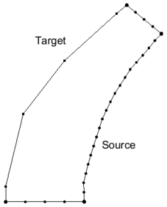
Before redistribution
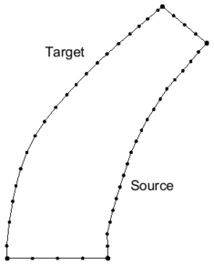
After redistribution


Reverse Arc Direction
This command (Feature Objects in the Map module or right-clicking on a selected arc) reverses the direction of all selected arcs. Arc orientation is only important for applications that use coastline or centerline arcs that have an arrow drawn on the arc.
Each arc has a direction. One node is the "from" node, the other node is the "to" node. For most applications, the direction of the arc does not matter. However, when the arc is used to define a observation plots, and in various other situations the direction of the arc becomes significant. The Reverse Arc Direction command can be used to change the direction (upstream to downstream) for an arc.
Smooth Arc

This command reduces the variability or roughness of an arc. Arcs may include variations (wiggles) and noise from the definition process. Smoothing an arc results in more gradual bends in the shape of the arc. Applying the smooth command repetitively will eventually result in a straight line.
An arc should not be smoothed, If the meanders and bends of an arc specifically depict a physical feature, smoothing will reduce the accuracy of this representation. Similarly, if an arc follows a contour line of a surface, smoothing the arc will make the arc not follow the contour as accurately. Smoothing may result in more gradual variations that can enhance numerical stability.
When the Smooth Arc command is used, the dialog that appears asks to specify the number of neighbors to be included in the smoothing window and a self weight. As the number of neighbors increases and the self weight decreases, the level of smoothing becomes more dramatic (moves to a straight line more quickly).
The algorithm computes a new position for each vertex in the arc from the existing vertex positions. The number of neighbors must be the same both before the vertex being smoothed and after. Since there are no vertices before the first node, and none after the last node, these two locations are not impacted by the smoothing process. The first vertex can be smoothed using the first node from before its position, and the first vertex after its position.
If the self weight is set to 1.0, no influence is assigned to the neighbors, so the arc does not smooth at all. If the self weight is set to 1/3, and the number of neighbors is set to 1, then each of the points has an even 1/3 weight in determining the new vertex location. If the self weight is set to 1/5, and the number of neighbors is set to 2, then five vertices impact the new location (Two vertices before the vertex in question and two vertices after) and the resulting point is the average of those five points (20% self weight, 80% neighbor weight with four neighbors).
Transform
See the article Data Transform
Select Connected Arcs
See the article Select Connected Arcs.
Create Arc Group
The Create Arc Group command is found in the Feature Object menu of the Map module. By selecting multiple arcs and using this command, the arcs will be made into a group. When selecting any one of the arcs in the group, all arcs in the group will be selected.
Create Contour Arcs

The Create Contour Arcs dialog is used to create a feature arc along a specified elevation of the active scatter dataset or cartesian grid elevation. To access the dialog do the following:
- Right-click on a Cartesian Grid or Scatter set in the Project Explorer.
- Select Convert then 2D Grid Contours→Map for Cartesian Grid, otherwise select Convert then Scatter Contours→Map. This brings up the Create Contour Arcs dialog. By default the active coverage is selected. A prompt will ask for the elevation and vertex spacing along contour.
The dialog allows specifying the following attributes:
- Destination Coverage – Clicking on this button will bring up a Select Tree Item coverage where an existing coverage can be designated to receive the contour arcs.
- Elevation – Designates an elevation level SMS will use to create the contour arcs. If the value enter does not match any of the existing elevation, no arcs will be generated.
- Spacing – Indicates the distance between vertices along the generated arcs.
Note: This command is the same as the Create Coastline command for CGWAVE.
Arc Attributes Dialogs
Feature Arc Attributes depend on the type of coverage being used. A purely geometric arc would have no special attributes, but arcs may be used to define specific types of features such as a coastline, open ocean boundary, stream thalweg, or edge of water. In addition, feature arcs may have model specific boundary condition definitions which should be applied to a geometric object of that model type at the location of the arc.
The Arc Attributes dialog is a dynamic dialog that will provide different options depending on the coverage type.

Recompute All Stations
This function (found in the Feature Objects menu) can be used if an arc's "Computational Length" value on a river changes. It sets the Start and End station values for each of the arcs with the same river name based on the computational lengths of each arc. So, for example, if there are 3 arcs in a river, the most downstream arc being 30 feet, the next arc being 40 feet, and the next arc being 50 feet, the starting and ending stations would be as follows for each of the arcs (Arc 1 is downstream):
Arc Start Station End Station 1 0.0 30.0 2 30.0 70 3 70.0 120.0
These start and end stations are set when assigning a river name to an arc, so there there should not be a need to use the Recompute All Stations command unless there is a change in the computational length, start station, or end station values for a centerline arc.
Prune Arc

Arcs may include more detail (features at a higher resolution) than are desired for an operation. For example, a coastline may include an inlet (and possibly an attached bay) that is too small to convey significant flow and would require excessive resolution to represent in a numerical model at the desired representation. This is more commonly the case when the arc in question is automatically generated from high resolution data or comes from other automated means. The "Prune" tool processes the arc to remove these unwanted "branches" from the arc. This can be thought of as an alternative to smoothing, but it actually just clips away the extraneous feature.
Situations/work flows that can benefit from this operation include:
- Removing inlets or rivers that extend inland from a modeled region at a resolution that is too high for the simulation.
- Removing meanders in an automatically defined flood plain or floodway boundary.
- Removing wiggles in automatically generated features (i.e. extracting features from a raster).
Depending on the orientation of the arc, the unwanted feature may be on the left side of the arc, or the right side of the arc. SMS can detect this situation when two non-neighboring segments of an arc are with in the specified distance of each on the side opposite to the side that is being pruned. Another way to think of this is that the segment of the arc between these to proximate segments represent a concave portion of the arc. Importantly, this tool can be used to remove concave sections along one side of the arc. Examples are included here.
Guidance
- The algorithm assumes that the first and last points of the arc will not be pruned.
- The prune tool was 'NOT' implemented to process an arc that forms a closed loop (an arc for which the starting and ending point are one and the same).
- It is the responsibility of the user to split arcs that form a loop into at least two arcs (convert at least one vertex to a node.)
- Starting and ending points (feature points, not vertices) should will not be pruned, so they should not be inside a region where pruning is desired.
- We recommend that start/end points should not even be directly adjacent to areas that are to be pruned if possible. (I.E. Not on the edge of an inlet.)
- Selecting points that are convex away from the trim side is best.

To prune an arc, right-click on the selected arc and select the Prune Arc(s) command. The Prune Arcs dialog has the following options:
- Feature width type – Select the method for pruning. Can be "Constant" or "Spatially varying".
- "Constant" – Uses a constant width is used for the entire length of the arc for determining possible concave areas.
- Width – The constant value used for pruning the arc.
- "Spatially varying" – Usees a size function to allow for different widths along the length of the arc.
- Select dataset – This table will show a tree of datasets available to use with the "Spatially varying" type. The domain of the dataset should cover the entirety of all arcs. The dataset will be linearly interpolated to each point of the arc to be used as a width to determine possible pruning. If the dataset is temporally varying, then the active time step is used.
- Truncate – If "Truncate" is checked, then the dataset values used for each point are truncated to be with Min and Max values. Min and Max are defaulted to the minimum and maximum values of the dataset at the active time step.
- "Constant" – Uses a constant width is used for the entire length of the arc for determining possible concave areas.
- Side to be pruned – Can be set to either "Left" or "Right". These values represent which side of the arc will be potentially pruned. "Left" and "Right" are relative to the direction of the arc.

Specify Arc Length

The Specify Arc Length tool can be used to create a new node/vertex a specified distance down the length of an arc. It is accessed by selecting an arc then right-clicking and selecting the Specify Arc length command. In the Specify Arc Length dialog, there is the following option:
- New Arc Length – Enter the desired arc length. The units for this length is either feet or meters based on projection.
- If specified length is less than arc length, a new node is added to the arc at the specified distance along the arc.
- If the distance specified is greater than the length of the arc, the end node of the arc is extended to make the arc length the specified distance.
Notes:
- This can change the shape of any arc attached to the end of the selected arc.
- This tool only operates on the arc in the defined arc direction.
Trim/Extend Arc

SMS can either trim or extend an arc to match the length of another arc. This is done by selecting two arcs then right-clicking and selecting the Trim/Extend Arc command. This command appears if two and only two arcs are selected. The Trim/Extend Arc dialog has the following options:
- Arc to be trimmed/extended – This option has a combo box of the two arc IDs. Select the arc that will be modified.
- Arc to trim/extend to – This option has a combo box of the two arc IDs. Select the arc that will be used as the source arc.
The Trim/Extend Arc tool determines the number of intersections between the two arcs. It uses the following principles to do this:
- The number of intersections included in the arc selection will indicate to the tool to use the "Extend" operation. This will do the following:
- Find the end point of arc 1 that is closest to arc 2. This is the point that will be moved.
- Extend the ending segment of the arc including the point to be moved to see if it intersects the trimming arc (arc 2). The tool will check to see if this operation can be done act as follows:
- If yes the tool will move the point that is being moved to the intersection.
- If no the tool will see if the last segment extended intersects either of the rays extending from the end of the trimming arc and do the following:
- If intersects both then the tool will move the point that is being moved to the nearest intersection.
- If intersects one the the tool will move the point that is being moved to the intersection.
- If intersects none the the will will display an error saying it can’t extend the arc.
- If 1 or more intersections are included in the selection, this indicates a "Trim" operation. The trim operation will do the following:
- Insert a node into the first arc at the first intersection.
- Delete the first portion of the newly split arc.
Create Horizontal or Vertical Segment
SMS allows creating horizontal or vertical segments when digitizing an arc. These are segments that are completely horizontal or completely vertical. This is done while digitizing an arc as follows:
- When creating the arc can hold down either the h or v key.
- If h is held down, the next point on the arc will be at the same Y value as the previous point.
- If the v is held down the next point on the arc will be at the same X value.
This process works similar to when creating the second direction of a grid frame.
Drag an Arc
SMS allows an arc to be offset graphically by doing the following:
- Selects an arc, hold down the D key, and hold down the mouse button (dragging). The button down (world location is saved)
- On button up, the button up world location is saved.
- The translation vector is computed as ButtonUpLoc - ButtonDownLoc.
- All nodes/vertices of the selected arc are translated by the translation vector.
- Note: this also impacts the arcs attached to the end points of the arc being dragged.
Selected arcs can be moved by selecting the arc, then, holding the mouse button down, dragging the arc to a new location. When doing this, if the arc shares a node with another arc, the nodes will be moved with the arc being moved and the attached arc will change its shape. Elevations assigned to the arc will stay the same, therefore it may be necessary to re-interpolate or assign elevations to the moved arc.
Related Topics
SMS – Surface-water Modeling System | ||
|---|---|---|
| Modules: | 1D Grid • Cartesian Grid • Curvilinear Grid • GIS • Map • Mesh • Particle • Quadtree • Raster • Scatter • UGrid |  |
| General Models: | 3D Structure • FVCOM • Generic • PTM | |
| Coastal Models: | ADCIRC • BOUSS-2D • CGWAVE • CMS-Flow • CMS-Wave • GenCade • STWAVE • WAM | |
| Riverine/Estuarine Models: | AdH • HEC-RAS • HYDRO AS-2D • RMA2 • RMA4 • SRH-2D • TUFLOW • TUFLOW FV | |
| Aquaveo • SMS Tutorials • SMS Workflows | ||