SMS:Map Module Selection
Beyond using the selection tools in the Map Module, there are a number of menu commands and dialogs that can be used to refine the selection of feature objects.
Select With Poly
Selects items associated with the current selection tool which are inside a user defined polygon. Create the polygon after selecting the command by clicking in the Graphics Window. The polygon is closed with a double-click. A similar feature called Select with Feature Polygon is available from the Map module. If a feature polygon is defined, it is possible to select nodes or elements in the mesh module or vertices in the data module that are inside or outside of the feature polygon.
Select By
The Select By option, in the Edit menu, allows selecting an object by its Material Type, Dataset Value, Area, Length, or Ambiguous Gradient.
- Material Type
- Selects all items of the current selection tool of a specified material. This command opens the Materials Data dialog with a list of the defined materials and waits for a material type to be selected. This enables all nodes or elements that reference a specific material to be selected together.
- Dataset Value
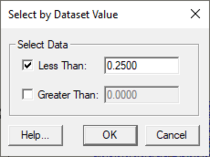
- Opens a dialog that asks to specify a range. All entities (nodes, elements, scatter points, etc.) of the current selection tool type whose scalar dataset value lies inside that range are selected. This enables all entities above or below threshold to be selected together for quick editing.
- Area
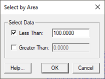
- Opens a dialog that asks to specify a range. All polygons whose area lies inside that range are selected. This enables all entities above or below threshold to be selected together for quick editing.
- Length
- Opens a dialog that asks to specify a range. All arcs whose length lies inside that range are selected. This enables all entities above or below threshold to be selected together for quick editing.
- Ambiguous Gradient
- Selects all elements in a mesh or cells in a grid where the directional flow is difficult to determine due to variation in the elevation at each node.
- BC Type
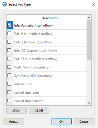
- Brings up a Select Arc Type dialog if the active coverage is a boundary conditions coverage (CMS-Flow, SRH-2D, TUFLOW, etc.). Allows selecting arcs by assigned boundary condition type.
Select Connected Arcs
As conceptual models become more complex, and include many arcs (possibly hundreds or thousands), detailed connectivity may not be visibly obvious. This means that it is possible to create or import arcs defining model extents or other features, that appear to be connected, but in actuality are not.
Select Connected Arcs Turning Left
The Select Connected Arcs Turning Left utility allows determining if a conceptual model has gaps in connectivity. The utility is used by right-clicking on a feature arc and selecting a Select Connected Arcs Turning Left submenu. There are two options for selecting the arcs, Forward and Backward. The Forward option follows the direction of the arc and the Backward option follows the opposite direction. This utility selects a string of connected arcs. If more than two arcs connect at a node, the utility selects the left-most turn. In a completely defined polygon, this will select all the arcs in the polygon and traverse right back to the starting arc.
If the Select Feature Polygon tool fails to operate as expected, this utility may identify the gaps in connectivity causing the polygons to not be defined correctly by the build polygon command.
Related Topics
SMS – Surface-water Modeling System | ||
|---|---|---|
| Modules: | 1D Grid • Cartesian Grid • Curvilinear Grid • GIS • Map • Mesh • Particle • Quadtree • Raster • Scatter • UGrid |  |
| General Models: | 3D Structure • FVCOM • Generic • PTM | |
| Coastal Models: | ADCIRC • BOUSS-2D • CGWAVE • CMS-Flow • CMS-Wave • GenCade • STWAVE • WAM | |
| Riverine/Estuarine Models: | AdH • HEC-RAS • HYDRO AS-2D • RMA2 • RMA4 • SRH-2D • TUFLOW • TUFLOW FV | |
| Aquaveo • SMS Tutorials • SMS Workflows | ||


