SMS:Feature Stamping

Feature stamping is the terminology used to refer to the insertion of man-made structures into a natural topography or bathymetry set. In common terms, this means adding an embankment (such as a levy) or dredging a channel. A stamped feature usually follows a linear object or centerline.
The Process
The basic steps to define a linear stamped feature include:
- Define the stamping coverage and centerline of the stamped feature
- Assign attributes to the centerline including:
- The elevation profile along the centerline
- The cross sections along the centerline
- Stamp the feature. This converts the centerline and its attributes to:
- Another coverage containing all the extents and details of the feature
- A scatter set defining the elevation for the feature.
Sample problems in the section below illustrate the procedure.
Define the Coverage and Centerline
SMS utilizes a coverage of type "Stamping" to create the stamped features. Depending on the application, it may be desirable to have multiple "Stamping" coverages to represent different design alternatives. Each coverage may contain multiple features. Create a "Stamping" coverage by right-clicking on the "Map Data" entry in the Project Explorer and selecting the New Coverage command. Then right-click on the new coverage and set its type to "Stamping".
The underlying geometry is defined by a scatter set (and one of its associated datasets). This surface determines the cut-off for the sloped banks of a stamped feature. Right-clicking on the coverage and selecting Stamping Properties brings up the Stamping Coverage Attributes dialog that associates a specific dataset to the stamping coverage. It's necessary to also specify whether this surface is defined as elevations (positive up) or depths (positive down). By default, SMS interprets this surface as elevation data.
The number of vertices along the centerline will determine the number of cross sections that will be created for the feature. For greater discretization of the feature, additional vertices may be added by redistributing the vertices along the centerline.

Define Feature Attributes
Any arc created in a "Stamping" coverage has attributes to create a stamped feature. For stamping arcs, the direction of the arc is important since attributes are assigned along the arc such as the starting and ending elevations.
Attributes are assigned in the Stamping Arc Attributes dialog. See Stamping Arc Attributes for more information.
Stamping the Feature

To create the stamped feature, right-click on the "Stamping" coverage and select Convert → Stamp Features .... This brings up a dialog that specifies what output should be created from the process. Specifically, the process can create:
- A new scatter set which defines the elevation points for the new structure. This is named based on the stamped feature name. SMS triangulates all these points to create a surface and trims the scatter set to the cutoff surface (if one has been specified in the coverage properties.) The arcs that make up the stamped feature are converted to scatter breaklines to assist in the triangulation.
- A new coverage which defines the breaks and extents of the stamped feature. The dialog specifies the type of the coverage to be created. Generally, it is recommended that the coverage type be selected to match the numeric engine that will eventually be used for the simulation.
- Options also exist to determine whether the stamped feature will include the center line, the shoulders, and the cross sections. The extents of the stamped feature are always generated. These options also control where breaklines are created on the scatter set.

Feature Stamping Dialogs
The available options on the dialogs used by the Stamping coverage are described below.
Stamping Coverage Attributes

The Stamping Coverage Attributes dialog will appear when creating a new stamping coverage. It can also be reached by right-clicking on the stamping coverage and selecting the Properties command.
- Underlying Geometry – This section contains options for defining the scatter set used in the stamping process.
- Use cutoff – Stamped features can be cut off where they intersect with a terrain surface dataset. Turn on this option to see available scatter sets that can be selected from the data tree. The scatter set will act as a surface to determine the cut off for the sloped banks of a stamped feature.
- Bathymetry Type – The bathymetry of the scatter set needs be specified for SMS to know how to stamp the feature.
- "Elevation" – The default option. Defines positive values as going up.
- "Depth" – Defines positive values as going down.
Stamping Arc Attributes
When an arc is used to stamp a feature, the elevation of the end nodes and vertices along the arc are used to define the top/bottom of the feature. Cross sections can be defined at each end node and vertex to define the width and shape of the feature at that specific location.

The Stamping Arc Attributes dialog is reached by double-clicking on an arc created in a stamping coverage. It can also be reached by right-clicking on the selected arc and using the Attributes command.
The following attributes can be set:
- Feature Name – This will be used when SMS creates stamped feature coverages and scatter sets from the stamping coverage.
- Stamping Type – Can be set to either create channel or embankment type features.
- "Cut Feature" – Will stamp the feature down from the surface, such as when stamping a channel or similar feature.
- "Fill Feature" – Will stamp the feature up from the surface, such as when stamping an embankment or similar feature.
- End Cap – Clicking the First End Cap or Last End Cap button will bring up the First End Cap or Last End Cap dialog. The first and last end cap is determined by the arc direction an are created at the end nodes of the arc.
- Centerline (CL) Profile – This section contains attributes for the nodes and vertices of the feature arc.
- CS – Lists a cross section ID for each node or vertex along the arc. The arrow in the column next to the ID indicates which node or vertex is being actively edited in the Cross Section (CS) section.
- Location on Arc – Shows the locating station of each node or vertex along the arc.
- Elevation/Depth – Displays the bathymetry value assigned to each node or vertex on the arc. This field can be edited.
- Constant → Elevation – Opens the Constant → Elevation. This dialog contains a field where a constant elevation can be specified for all points and vertices along the center line.
- XY Series → Elevation – Opens the XY Series Editor where elevations can be entered as a curve. SMS will match the center line point or node elevation to the curve. The curve data must define a curve that is at least as long as the length of the arc.
- Plot CL Profile – Turning on this option will bring up a profile plot of the centerline. The profile plot can be kept open to see changes in the centerline as they are made in the Stamping Arc Attributes dialog.
- Cross Section (CS) – This section defines the cross section geometry. It only shows the values for the current selected node or vertex in the Centerline (CL) Profile section. The cross section can be defined as a template, which is propagated all along an arc, or can be individually specified at each vertex in an arc. The left and right sides, with reference to the centerline, of the cross section are both defined individually in this section.
- Left Side – The geometry for the left side of the cross section is defined in this section. The left side is determined by the starting point (station 0) of the centerline arc.
- Right Side – The geometry for the right side of the cross section is defined in this section. The right side is determined by the starting point (station 0) of the centerline arc.
- Elevation/Depth – Defines the elevation of each cross section point.
- Shoulder – One point on each side of the cross section can be specified as the "shoulder". For a channel, this would be the "toe", but the reference in SMS is the shoulder point. When the arcs representing the shoulder are created, the option is available to create an arc along this shoulder. If vertical walled structures are desired, the cross section can simply stop at the edge (shoulder). This will result in a feature arc at the edge and a scatter set for the top of the structure.
- Maximum Distance from CL – This input specifies the maximum horizontal distance away from the centerline that the specified embankment side slope will extend. It is recommended that this value be something large enough so that the toes of the embankments will extend below the terrain surface elevations that are used as a cutoff surface. This will make the embankment and terrain surface intersection continuous without vertical gaps. The slope calculated between the last two cross section points entered in the left and right side sections will be carried out to this distance.
- Specify Top Width and Single Side Slopes – Opens the Top Width and Side Slopes dialog. This can be used to quickly define a trapezoidal cross section for a cut or fill feature.
- Top Width – This defines the top width of the fill feature or the bottom width of a cut feature.
- Left Slope – This defines the left slope of the trapezoidal cross section. Entering "1" would be equivalent to a 1:1 slope. Enter negative values for fill (embankment) type features.
- Right Slope – This defines the right slope of the trapezoidal cross section. Entering "1" would be equivalent to a 1:1 slope. Enter negative values for fill (embankment) type features.
- Current CS → All CS – Copies the current cross section definition to all other cross sections. This creates a uniform embankment across the entire length of the arc.
- Plot Current CS – Turning on this option will bring up a profile plot of the current cross section. The profile plot can be kept open to see changes in the cross section as they are made in the Stamping Arc Attributes dialog.

End Cap

The Left End Cap and Right End Cap dialogs are used to determine how the feature will terminate at the end of the arc. It is not required to define the end caps. These dialogs are reached through the Stamping Arc Attributes dialog.
- Type of end cap – Three types of end caps are supported.
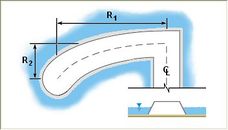
- "Guidebank" – This this end cap will move away from the end of the centerline arc, either to the left or right of the arc direction.
- Side – Specifies whether the guidebank will move to the "Left" or "Right" of the centerline arc.
- Radius 1 – The distance from the end of the centerline arc to the end of the guidbank.
- Radius 2 – The distance the end of the guidbank will be curved back from the end of the centerline arc.
- Number of Points – The number of vertices created when extending the centerline to create the guidebank.
- Width – How wide the guidebank will be.
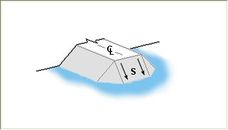
- "Sloped Abutment" – Creates a simple slope end cross section to the bathymetry.
- Slope – This table defines how the slope abutment should be shaped from the centerline. The distance and bathymetry will be used to define the shape of the slope.
- Distance from, CS – The distance from the last cross section (arc end node) for a point on the abutment slope.
- Elevation/Depth – The elevation of the abutment slope at the specified distance from the last cross section.
- Maximum Distance from CS – Specifies how far the end cap can extend past the end cross section and still intersect with the bathymetry. Distance values past this value will be left off. In general, SMS will try to follow the shape of the slope defined in the table, but will make adjustments in order to not exceed the maximum distance from the centerline.
- Plot Shape – Clicking this option will bring up a plot window showing how the sloped abutment will be shaped.
- Slope – This table defines how the slope abutment should be shaped from the centerline. The distance and bathymetry will be used to define the shape of the slope.
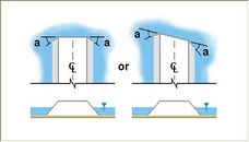
- "Wing Walls" – Bevels the edges of the cross sections at a specified angle for the end cross section of the feature stamp.
- Wing wall angle – Indicates how much far back the ends of the cross section will move towards the centerline. The range of acceptable values is from 0 to 60 degrees.
- "Guidebank" – This this end cap will move away from the end of the centerline arc, either to the left or right of the arc direction.
- Angle – Defines the angle of the end cap in relation to the end of the centerline arc. After entering a value, the image below this field will update to indicate how the end cap will change. The range of acceptable values is from -45 to 45 degrees.
Guidebank
Sloped Abutment
Wing walls


Stamp Features

When using the Feature Objects | Stamp Features menu command, the Stamp Features dialog appears. The dialog has the following options:
- Stamping Options
- Stamp to Scatter Set – This option will create a new scatter set which defines the elevation points for the new structure. This is named based on the stamped feature name. SMS triangulates all these points to create a surface and trims the scatter set to the extents of the stamped feature. The arcs that make up the stamped feature are converted to scatter breaklines to assist in the triangulation.
- Stamp to Coverage – This option will create a new coverage with the defined breaks and extents of the new feature.
- Coverage Type – This option contains a list of all available coverage types. Generally, it is recommended that the coverage type be selected to match the numeric engine that will eventually be used for the simulation.
- Stamp to centerline arc – The centerline arc will be included in the stamped feature on the scatter set and/or coverage.
- Stamp cross sections – All cross sections will be included in the stamped feature on the scatter set and/or coverage.
- Stamp shoulders – All shoulders will be included in the stamped feature on the scatter set and/or coverage.
Case Studies / Sample Problems
There are a wide variety of stamped features that can be created using this tool. The Feature Stamping tutorial in the general section of the tutorials may be helpful for learning to use them.
- Embankments on a flat plain
- Vertical sides on an embankment
- Sloped sides on an embankment
Related Topics
External Links
- Emery, R. N. (2005). Refining and Expanding the Feature Stamping Process. Thesis, Brigham Young University. [1]
- Christensen, J. R. (2001). Stamped Features: Automatic Generation of Flow Modifying Structures in Conceptual Models. Thesis, Brigham Young University.
- Zundel, Alan K. and J. Ryan Christensen, “Stamped Features: Creation of Engineered Structures in Conceptual Models”, International Journal of Hyrdroinformatics, Vol. 4, No. 1, February 2002, pp. 63-72.
| [hide] SMS – Surface-water Modeling System | ||
|---|---|---|
| Modules: | 1D Grid • Cartesian Grid • Curvilinear Grid • GIS • Map • Mesh • Particle • Quadtree • Raster • Scatter • UGrid |  |
| General Models: | 3D Structure • FVCOM • Generic • PTM | |
| Coastal Models: | ADCIRC • BOUSS-2D • CGWAVE • CMS-Flow • CMS-Wave • GenCade • STWAVE • WAM | |
| Riverine/Estuarine Models: | AdH • HEC-RAS • HYDRO AS-2D • RMA2 • RMA4 • SRH-2D • TUFLOW • TUFLOW FV | |
| Aquaveo • SMS Tutorials • SMS Workflows | ||