WMS:GSSHA Groundwater: Difference between revisions
No edit summary |
|||
| Line 23: | Line 23: | ||
*Head river | *Head river | ||
WMS automatically generates Gw Boundary and Wells [[WMS:GSSHA Index Maps|index maps]], according to the groundwater boundary conditions conceptualized using feature points/nodes and arcs on the GSSHA coverage, when the Groundwater option is toggled on in the Job Control. These index maps will appear in the Index Maps folder of the Project Explorer and are useful for visualizing boundary conditions and well locations/pumping rates. If wells are defined then the Wells map table, which is not visible in the [[WMS:GSSHA Mapping Tables|Map Tables dialog]], is also populated when the Wells index map is created. Any changes that are made to either the boundary conditions or wells require that you regenerate the index maps (and wells map table) by right-clicking on either of the index maps in the Project Explorer and selecting the Regenerate command. | WMS automatically generates Gw Boundary and Wells [[WMS:GSSHA Index Maps|index maps]], according to the groundwater boundary conditions conceptualized using feature points/nodes and arcs on the GSSHA coverage, when the ''Groundwater'' option is toggled on in the ''Job Control''. These index maps will appear in the Index Maps folder of the Project Explorer and are useful for visualizing boundary conditions and well locations/pumping rates. If wells are defined then the Wells map table, which is not visible in the [[WMS:GSSHA Mapping Tables|Map Tables dialog]], is also populated when the Wells index map is created. Any changes that are made to either the boundary conditions or wells require that you regenerate the index maps (and wells map table) by right-clicking on either of the index maps in the Project Explorer and selecting the '''Regenerate''' command. | ||
The groundwater boundary condition map and, if necessary, the well index map and map table are also written when the GSSHA .prj file is saved. | The groundwater boundary condition map and, if necessary, the well index map and map table are also written when the GSSHA *.prj file is saved. | ||
==Global Parameters== | ==Global Parameters== | ||
Revision as of 19:16, 4 February 2013
Groundwater interaction in GSSHA models can only be performed in conjunction with one of the following infiltration methods:
- Green & Ampt with soil moisture redistribution
- Richards' equation
To model groundwater interaction in a GSSHA model:
- Assign groundwater boundary conditions conceptually to feature points/nodes and arcs on the GSSHA coverage.
- Toggle on the Groundwater option in the Job Control and set the global parameters.
- Toggle on the Sub-surface losses/gains option for GSSHA stream arcs in order to model groundwater interaction with the GSSHA channel network. (optional)
Groundwater Boundary Conditions
WMS can assign these boundary conditions to feature points/nodes:
- Generic
- Constant head
- Static well
- Dynamic well
The following groundwater boundary conditions are allowed for feature arcs:
- Generic
- No flow
- Constant head
- Flux river
- Head river
WMS automatically generates Gw Boundary and Wells index maps, according to the groundwater boundary conditions conceptualized using feature points/nodes and arcs on the GSSHA coverage, when the Groundwater option is toggled on in the Job Control. These index maps will appear in the Index Maps folder of the Project Explorer and are useful for visualizing boundary conditions and well locations/pumping rates. If wells are defined then the Wells map table, which is not visible in the Map Tables dialog, is also populated when the Wells index map is created. Any changes that are made to either the boundary conditions or wells require that you regenerate the index maps (and wells map table) by right-clicking on either of the index maps in the Project Explorer and selecting the Regenerate command.
The groundwater boundary condition map and, if necessary, the well index map and map table are also written when the GSSHA *.prj file is saved.
Global Parameters
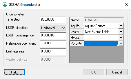
Enter parameters that control the groundwater computations in the GSSHA Groundwater dialog. The Aquifer cell size parameter is the vertical cell size used with Richard's infiltration. Specify continuous data sets used to define the aquifer bottom and water table. Hydraulic conductivity and porosity can be defined using continuous data sets or by assigning parameters in the Groundwater map table based on an index map generated using soil type data.
WMS writes all global groundwater parameters to the GSSHA .prj file. The groundwater map table (hydraulic conductivity and porosity) will be written to the .cmt file if Ids exist. Otherwise, hydraulic conductivity and porosity must be specified as continuous maps.
Channels
Interaction between the groundwater and the channel network is controlled for each link by toggling on the Sub-surface losses/gains option and specifying a sediment thickness and hydraulic conductivity. These values are written to the .cif file.
Related Topics
- GSSHA Continuous Maps
- GSSHA Feature Arcs
- GSSHA Feature Nodes
- GSSHA Index Maps
- GSSHA Job Control
- GSSHA Map Tables
GSSHA | |
|---|---|
| XMS Wiki Links | Calibration (Automated • Manual • Output) • Channel Routing • Contaminants • Digital Dams • Embankment Arcs • Feature Objects (Arcs • Nodes • Polygons) • File Types • Groundwater • Groups • Hydraulic Structures • Job Control • Join SSURGO Data • Mapping Tables • Maps • Menu • Model Linkage • Multiple Simulations • Nutrients • Observations • Output Control • Overland Soil Erosion • Pipe and Node Parameters • Precipitation • Radar Rainfall • Save GSSHA Project File • Smooth GSSHA Streams • Snowmelt • Solution (Analysis • Data) |
| Related Tools | MWBM Wizard • Using Soil Type Data with GSSHA |
| GSSHA Wiki External Links | GSSHA Wiki: Overview • Primer • User's Manual • Tutorials |
