SMS:SRH-2D Material Properties
The SRH-2D model has its own materials options. These options become available when SRH-2D is active. Individual SRH-2D items may have their own material properties. This allows having more than one set of material definitions in SRH-2D.
The SRH-2D Materials coverages should be used for assigning materials to an SRH-2D simulation.
Dialog Description
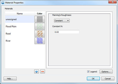
The SRH-2D Material Properties dialog is accessible from the menu command Edit | Materials Data when an SRH-2D item is active. When the active item is not specified as part of SRH-2D, using the Materials Data command will bring up the global Materials Data dialog.
The Material Properties dialog can also be reached by right-clicking on an SRH-2D materials coverage item in the Project Explorer and selecting the Material Properties command. Right-clicking on a polygon with the Polygon Selection tool and choosing the Assign Material Properties command will also bring up the Material Properties dialog.
The Material Properties dialog is sometimes labeled as the Assign Material Properties dialog. The Material Properties dialog windows has the following elements:
Materials List
The Materials list contains two columns (Name, and Color) for the defined materials. The default "unassigned" material cannot be edited (except the display pattern) and will always be at the top of the spreadsheet regardless of sorting. Each material is accompanied by a Color button in the Color column. To select a color and pattern, click on the button to open the Choose window.
On the right side of the dialog, the numeric properties of the material are displayed and can be edited. SRH-2D needs a Manning's roughness value for each material in the list. This valloaue can be a constant or it can be varied based on depth. Typical values of roughness vary from 0.015 which is characteristic of a smooth finished concrete surface, to 0.02–0.03 for natural channels up to 0.1–0.15 for very dense vegetation or areas with large obstructions like buildings.
The list of materials can be defined interactively or loaded from another source. Sources include another SRH-2D materials coverage or a GIS polygon coverage attribute table. When using a GIS coverage, the entire material coverage can be defined including the polygon definitions, the materials list and the N value for each material in the table. Any combinations of these can be utilized when the information is included in the shapefile and desired in the model. See Using GIS data to populate material polgons and attributes for more information.
Choose Window
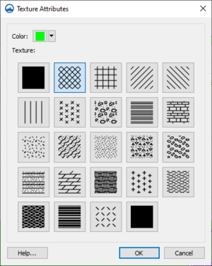
Clicking on the button under the Color column will open a new Choose dialog. In the Choose window, to quickly edit only the color, click on the down arrow (right side) of the button, and make a selection in the pop up color palette. For more color options, click on the color button to bring up the Select Color dialog. Select a pattern by making a selection in the Texture section of the Choose window.
Insert and Remove Buttons
 – Inserts a material into the spreadsheet with the lowest unique ID available and a default name and pattern.
 – Removes the currently selected material from the spreadsheet.
Manning's Roughness Coefficient
This section of the Material Properties dialog edits the Manning's n or depth varied n for the select material. By default, a single default Manning's n of "0.02" is assigned by SMS if no Manning's n is indicated. It is possible to select multiple n values as a function of depth and then enter depth/n pairs.
The Manning's n value can be set to a "Constant" or "Depth Varied" value. The "Depth Varied" option will display an option to enter values in an XY Series Editor.
This section only appears when the SRH-2D Material coverage is the active coverage. Does not appear with the SRH-2D Sediment Materials coverage.
Sediment Material Properties
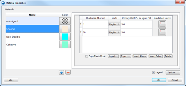
The SRH-2D model has specific sediment materials requirements. When the SRH-2D Sediment Material coverage is active, the options in this section change.
Each material polygon or group of polygons is assigned multiple sediment layers. Layers are added using the Insert Above and Insert Below buttons. A selected layer can be removed using the Delete button. Layers can also be added using the Import to bring layer data from a text file. The Copy/Paste Mode also pasting data from another program or copying the data to another program.
Each layer can specify a Thickness, thickness Units, site dry bulk Density, and sediment Gradation Curve.
A minimum of two layers is recommended even if the bed material is vertically uniform: one relatively thin layer to interact with the sediment transport and a thicker sediment reservoir. In sand bed rivers the two layers typically have the same densities and gradations. For gravel bed rivers the upper layer can represent a coarse surface armor and the deeper layer is the subsurface gradation.
Legend
- Legend – Check box with the associated Options... button controls the display of a legend of the materials in the Graphics Window.
- Options... – Opens the Legend Options dialog. The options for the legend are edited in the Legend Options dialog. These options are the same as in the Materials Data dialog.
Related Topics
SMS – Surface-water Modeling System | ||
|---|---|---|
| Modules: | 1D Grid • Cartesian Grid • Curvilinear Grid • GIS • Map • Mesh • Particle • Quadtree • Raster • Scatter • UGrid |  |
| General Models: | 3D Structure • FVCOM • Generic • PTM | |
| Coastal Models: | ADCIRC • BOUSS-2D • CGWAVE • CMS-Flow • CMS-Wave • GenCade • STWAVE • WAM | |
| Riverine/Estuarine Models: | AdH • HEC-RAS • HYDRO AS-2D • RMA2 • RMA4 • SRH-2D • TUFLOW • TUFLOW FV | |
| Aquaveo • SMS Tutorials • SMS Workflows | ||


