SMS:GIS Module Menus
From XMS Wiki
Jump to navigationJump to search
The following menus are available in the the GIS Module:
Standard Menus
See SMS Menus for more information.
Module Specific Menus
Data
Most of the SMS modules have a Data menu, but the items in this menu are different for each module. The GIS Module commands include:
- Add Shapefile Data
- The Add Shapefile Data command is only available if ArcObjects® have not been enabled. The Add Shapefile Data command is used to open a Shapefile (*.shp) into SMS.
- Add MIF/MID File Data
- SMS uses ArcObjects® to incorporate much of the ArcMap® functionality directly. SMS can open any ArcGIS® supported file (coverages, shapefiles, geodatabases, images, CAD, grids, etc.) and use the ArcGIS® Display Symbology properties to render the GIS data and then display it in SMS.
- The Add MIF/MID Data command is used to open a MIF/MID file (*.mif) into SMS using ArcGIS®.
- Layer Properties
- The Layer Properties command opens the Select a layer dialog. The shapefile layer of interest is specified in the Select a layer dialog. Once the shapefile layer has been specified, the Layer Properties dialog is shown. See the ArcGIS® documentation for further explanation of the Layer Properties dialog. The Layer Properties command is only available if ArcObjects® have been enabled.
Mapping
The GIS Module Selection menu commands are only available if ArcObjects® have been enabled. The GIS Module Selection menu commands include:
- Shapes → Feature Objects
- Opens the GIS to Feature Objects Wizard.
- Polygons → TIN
- Converts polygon data to TIN data that will appear in the scatter module.
GIS Module Right-Click Commands
Right-clicking on an object in the GIS Data folder ![]() of the Project Explorer pops up a menu of appropriate commands for the specific object type (static image, DEM, dynamic image, GIS coverage, ...) The following right-click commands are available for GIS objects.
of the Project Explorer pops up a menu of appropriate commands for the specific object type (static image, DEM, dynamic image, GIS coverage, ...) The following right-click commands are available for GIS objects.
- Delete or Remove – Deletes the GIS object from the project. This does not delete any file on disk (image files or GIS data files such as shapefiles) that are storing the objects.
- Rename – Available for dynamic images and coverages. Allows specifying the name that appears on the Project Explorer. Apostrophes and special characters should not be used in the new name.
- Transparency – Brings up the Layer Transparency dialog. Available for raster objects or images for both static and dynamic images.
- Zoom to Extents – Frames and centers the graphics window to the extents of the selected object. Available for static images and DEMs as well as coverages. Since a dynamic image refreshes to whatever extents are being viewd, this command is not available for these objects.
- Open Containing Folder – Launches a file explorer window in the directory containing a static image. The command is not available for other object types.
- Projection/Set Layer Projection – Brings up the Object Projection dialog. This command is not available for dynamic images because.
- Register Image – Brings up the Register Image dialog. Available for static images and DEMs.
- Export – Brings up a dialog to resamples and save the image. Available for static images and DEMs.
- Export World File – Exports a world file for the object that includes image registration data. Available for static images and DEMs.
- Crop Collar – Turns on or off the optionally transparent pixels around the edge of an image. This is typical for USGS quad sheets. Available for static images and DEMs.
- Interpolate To – This sub-menu appears for static images and DEMs. However, if the image does not have elevation data (DEM), the command does nothing. When the image has numeric data such as elevation or land use classifications (NLCD), a sub-menu for commands to interpolate the GIS object into another geomteric object in the project including:
- 2D Mesh
- 2D Scatter (both as regular scatter set and as land use data for ADCIRC nodal attributes)
- 2D Grid
- UGrid
- Active coverage
- Convert To – This sub-menu contains commands which vary with the selected object.
- GIS Coverage – For a GIS coverage a sub-menu appears with the options to convert GIS points, arcs and polygons to geometric objects of another type along with any appropriate attributes. The conversion options include:
- Shapes → Feature Objects – This command is a very powerful option for converting the feature points, arcs and polygons in the GIS coverage to feature objects in an SMS specific coverage. The command brings up a the GIS to Featue Objects Wizard. This allows the user to first specify the target feature coverage (which must be created before invoking this command) and the source GIS coverage or coverages to be converted. With the source and target specified, the next step of the wizard brings up the attribute mapping dialog (for polygons, arcs, or points depending on the type of GIS coverage(s) specified as the source).
- The user then maps the source attributes from the GIS coverage to the attributes of the selected feature coverage based on the coverage type. This will create the geometric objects as well as assign their attributes.
- Polygons → TIN – This command will convert all polygons in the GIS coverage to breaklines in a TIN and triangulate all the points.
- Dynamic images – For a dynamic image, the only option for conversion is to convert to a static image. This will ask the user for a sampling ratio and a file name to create the static image. By default, SMS will load the static image into the current project.
- Static images – For a static image or DEM a sub-menu appears with the options to convert to other data types. If the image does not have numeric data, it can only be resampled. However, if the image has numeric data such as elevations or land use classifications the following conversions are supported:
- 2D Scatter – Each pixel is converted to a scatter point or vertex.
- 2D Grid – A Cartesian grid is created with each pixel mapped to a cell.
- Feature Contours – Contour(s) of the data in the DEM.
- Feature Contours at Given Elevation
- Resampled Raster – Creates a new DEM covering the bounds of the selected DEM with a specified spacing.
- Smoothed Raster – Smooths the values on the DEM based on use specified weighting functions.
- Trimmed Raster – Trims to the bounding box of a coverage or selected polygons.
- Flood Depths – Creates an inundated depth raster by using the elevation raster and a surface water elevation dataset.
- Merged Raster – Appears when multiple rasters are selected. It creates a new raster that covers all selected rasters with a resolution set to the smallest cell size of any of the selected rasters.
- See the article GIS Conversion and Editing for more information.
- Editing – For DEM data (static images with numeric data), a sub-menu with the following commands:
- Arc Elevation Profile – Brings up the Profile Elevations plot for a selected arc.
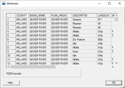
- Open Attribute Table – The Attribute Table command opens the Attribute dialog. The attributes for each record in the specified layer can be viewed.
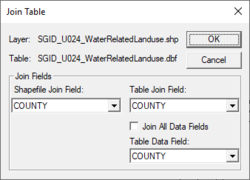
- Join Table to Layer – Allows joining the attributes of one database file (*.dbf) to the features of a GIS layer based on a key attribute field. This is particularly important when the features are stored in a shapefile with a minimal set of attributes, and additional attributes are stored in a separate *.dbf file. The two files are related based on an attribute field named MUID. Other GIS data layers may be similar where the features contain some kind of key indexing field and the attributes are stored in a separate table that can be joined to the features based on the index field values.
- After selecting the Join Table to Layer command a prompt will appear for the database file to join using the standard Select File dialog. The Join Table dialog will then appear and ask to select the Join Field from the GIS data layer attributes and the Join Field from the table being joined to the GIS data layer. Often these field names will be the same as in the example below, but they are not required to be the same. The important thing is that they contain similar information from which a join can be made. Finally, select to join all of the attributes from the join table or just add a specific field.
- The join does not permanently alter the GIS data layer on the hard drive of the computer.
- Convert to TUFLOW Rainfall Boundary Conditions – If the format is correct, the GIS data can be converted into TUFLOW rainfall boundary polygons on a TUFLOW 1D/2D BCs and Links coverage. For more information, see TUFLOW Boundary Conditions.
Related Topics
SMS Menu Bars | |
|---|---|
| Standard Menus: | File • Edit • Display • Window • Help |
| Module Menus: | 2D Mesh • Cartesian Grid • Curvilinear Grid • GIS • Map • Particle • Quadtree • Raster • Scatter |
| Model Menus: | ADCIRC • BOUSS-2D • CGWAVE • CMS-Flow • CMS-Wave • FESWMS • Generic Model • GenCade • PTM • RMA2 • RMA4 • SRH-2D • STWAVE • TUFLOW |
SMS – Surface-water Modeling System | ||
|---|---|---|
| Modules: | 1D Grid • Cartesian Grid • Curvilinear Grid • GIS • Map • Mesh • Particle • Quadtree • Raster • Scatter • UGrid |  |
| General Models: | 3D Structure • FVCOM • Generic • PTM | |
| Coastal Models: | ADCIRC • BOUSS-2D • CGWAVE • CMS-Flow • CMS-Wave • GenCade • STWAVE • WAM | |
| Riverine/Estuarine Models: | AdH • HEC-RAS • HYDRO AS-2D • RMA2 • RMA4 • SRH-2D • TUFLOW • TUFLOW FV | |
| Aquaveo • SMS Tutorials • SMS Workflows | ||

