GMS:Color Ramp
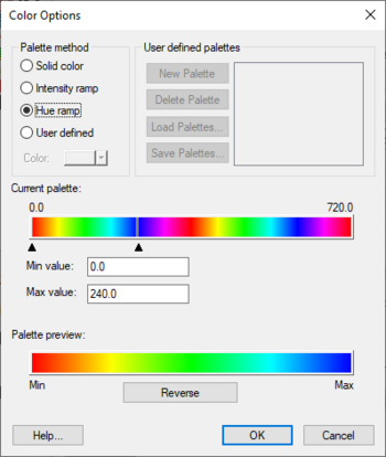
Several of the display options (contours, isosurfaces, color-shaded vectors, etc.) use a color ramp to vary the display color based on a relative value. The color ramp can be edited by selecting the Color Ramp command in the Contour Options dialog. This dialog is also available as part of the options for other parts of GMS. The Color Options dialog contains the following options:
Palette Method
The Palette Method section lists the four basic options for defining the color ramp:
Solid color
Defines a single color that will be used for the contours. Usually best for linear contours without any color fill.
Intensity Ramp
The Intensity Ramp option defines a ramp of colors corresponding to varying intensities of a single color.
Hue Ramp
The Hue Ramp option defines a ramp of color hues (red-yellow-green-blue-magenta) at the maximum color intensity.
User-Defined
If the User-Defined option is selected, a user-defined color palette is used to define the color ramp.
User-Defined Palettes
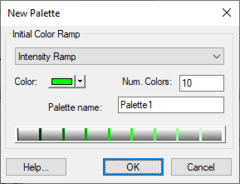
The user-defined color palettes are listed in the upper right corner of the Color Options dialog. A new palette is created by selecting the New button. This button brings up the New Palette dialog, listing a set of options for defining the initial color palette. These colors can be edited using the Current Palette section of the Color Ramp Options dialog. An existing palette can be deleted using the Delete Palette button.
Once a set of user-defined color palettes are created, they are saved with the project to a palette file (*.pal). The Load palettes and Save Palettes buttons can be used to share user-defined palettes between projects.
Current Palette
The current color palette is displayed in the Current Palette section. When the "Intensity ramp" or "Hue ramp" options are selected, the min and max value of the color ramp can be set by clicking and dragging the two triangles just below the color palette.
User-defined Color Palettes
There are several options unique to User-defined color palettes.
- Add Value – This tool's icon is paint bucket. When this tool is selected, clicking in the current color palette adds a new value and color at the specified location.
- Select Value – This tool's icon is an arrow pointing at a line. Select a value in the palette to edit its associated value. Double-click a value to open a Color dialog allowing for editing the color associated with a value. The data value associated with a selected color can be edited either by dragging the color in the palette or by entering a new value directly in the Value box.
- Display values as – The values can be displayed as either percentages or direct values (corresponding to the active dataset).
- Edit Table – Opens a Color Table dialog used to edit the colors and corresponding values directly in a tabular format. To delete a color and its corresponding value, simply clear the Value column in this dialog and click OK.
Palette Preview
The Palette preview section at the bottom of the Color Options dialog displays the color ramp defined by the current palette and max and min values. The Reverse button can be used to reverse the direction of the color ramp (for example, to switch from red-yellow-green-blue to blue-green-yellow-red).
See also
GMS – Groundwater Modeling System | ||
|---|---|---|
| Modules: | 2D Grid • 2D Mesh • 2D Scatter Point • 3D Grid • 3D Mesh • 3D Scatter Point • Boreholes • GIS • Map • Solid • TINs • UGrids | |
| Models: | FEFLOW • FEMWATER • HydroGeoSphere • MODAEM • MODFLOW • MODPATH • mod-PATH3DU • MT3DMS • MT3D-USGS • PEST • PHT3D • RT3D • SEAM3D • SEAWAT • SEEP2D • T-PROGS • ZONEBUDGET | |
| Aquaveo | ||

