User:Rcorrigan: Difference between revisions
No edit summary |
No edit summary |
||
| Line 1: | Line 1: | ||
[[User:Rcorrigan/Workflow Tests|Workflow Tests]] | [[User:Rcorrigan/Workflow Tests|Workflow Tests]] | ||
[[Category:User:Rcorrigan/Templates]] | |||
==TUFLOW FV Model Control editing== | ==TUFLOW FV Model Control editing== | ||
====General==== | ====General==== | ||
Revision as of 22:34, 22 February 2022
TUFLOW FV Model Control editing
General
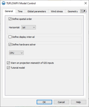
The General tab of the TUFLOW FV Model Control dialog contains the following options:
- Define spatial order – (Option to define horizontal spatial scheme??)
- Horizontal – Select "1st" order scheme or "2nd" order scheme
- Define display interval
- Display interval
- Define hardware solver
- CPU
- GPU
- Device ID
- Warn on projection mismatch of GIS inputs
- Tutorial model
Time
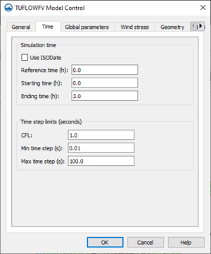
The Time tab of the TUFLOW FV Model Control dialog contains the following options:
- Simulation time
- Use ISODate
- Reference time
- Starting time
- Ending time
- Time step limits
- CFL
- Min time step(s)
- Max time step(s)
Global parameters
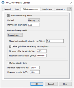
The Global parameters tab of the TUFLOW FV Model Control dialog contains the following options:
- Define bottom drag model
- Method
- "Manning"
- Manning's n coefficient
- "KS"
- Nikuradse roughness
- "Manning"
- Method
- Horizontal mixing model
- "None"
- "Constant"
- Global horizontal eddy viscosity
- "Smagorinsky"
- Global horizontal eddy viscosity
- Define global horizontal eddy viscosity limits
- Minimum eddy viscosity
- Maximum eddy viscosity
- "Wu"
- Global horizontal eddy viscosity
- Define global horizontal eddy viscosity limits
- Minimum eddy viscosity
- Maximum eddy viscosity
- Define stability limits
- Maximum water level
- Maximum velocity
Wind stress
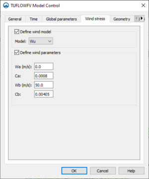
The Wind stress tab of the TUFLOW FV Model Control dialog contains the following options:
- Define wind model
- Model
- Wu
- Constant
- Kondo
- Model
- Define wind parameters
- Wa
- Ca
- Wb
- Cb
- Bulk momentum transfer coefficient
- Scale factor
Geometry
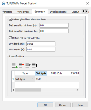
The Geometry tab of the TUFLOW FV Model Control dialog contains the following options:
- Define global bed elevation limits
- Bed elevation minimum
- Bed elevation maximum
- Define cell wet/dry depths
- Dry depth
- Wet depth
- Z modification
- Add Row
- Delete Row
- Move up
- Move down
- Type
- Set Zpts
- GRID Zpts
- CSV File
- CSV Type
- ZLine Shapes
- ZPoint Shapes
Initial conditions
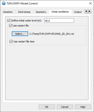
The Initial conditions tab of the TUFLOW FV Model Control dialog contains the following options:
- Define initial water level
- Use restart file
- Select
- Use restart file time
Output
The Output tab of the TUFLOW FV Model Control dialog contains the following options:
Materials
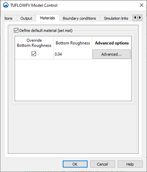
The Materials tab of the TUFLOW FV Model Control dialog contains the following options:
- Define default material (set mat)
- Override Bottom Roughness
- Bottom Roughness
- Advanced Options
Boundary conditions
The Boundary conditions tab of the TUFLOW FV Model Control dialog contains the following options:
- Define BC default update dt
- BC default update dt
- Run in transport mode
- Transport BC file
- Global boundaries
- Add row
- Delete row
- Gridded boundaries
- Add row
- Delete row
- Global wave options
- Include wave stress
- Include Stokes drift
Simulation links
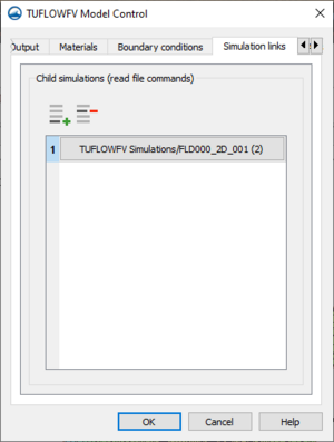
The Simulation links tab of the TUFLOW FV Model Control dialog contains the following options:
- Add row – Brings up the Select Child TUFLOW FV Simulation dialog. In this dialog another TUFLOW FV simulation can be select to link as a child simulation to the current simulation.
- Delete row – Unlinks the selected simulation.
Advanced
The Advanced tab of the TUFLOW FV Model Control dialog contains the option to include advanced options These options can be added in the text editor located in this tab. The text will be appended to the FVC file with the simulation is exported.
Model Control Editing
Parameters
- Source terms – (This option defines whether CMS-Wave should generate waves using wind input or not.???)
**"Source terms and propagation" – Uses wind input if provided. **"Propagation only" – Neglects wind input in calculation. *Current interaction – Option to define currents for the simulation.
- "None" – No current interaction will be in the simulation.
- "Use dataset" – A vector dataset can be used to define the currents for the simulation. Click Select to select from the dataset options in a dialog.
- "Gauss-Seidel" – Sets matrix solver to Gauss-Seidel solver with multi-processor capability.
- Number of threads –
- "ADI" – Sets matrix solver to Alternative Direction Iterative solver.
- "Gauss-Seidel" – Sets matrix solver to Gauss-Seidel solver with multi-processor capability.
Source Material
- Source Terms – Specifies whether STWAVE should generate waves using wind and the input spectrum or whether to use the wave spectrum.
Boundary Control
The Boundary control tab contains options for assigning spectral data for the model run.
- Source – Select the source for the external boundary conditions
- "Spectral Coverage" – Uses the spectral coverage in the simulation for all boundary conditions.
- "None" – Requires that energy spectra be entered.
- Interpolation Type – Sets the method for (CMS-Wave??) to use when interpolating between spectra.
- "Average spectra" –
- "IDW interpolation" – Sets the type of data interpolation to Inverse Distance Weighting
- Computational Spectral Grid – Adjust and view data related to the computational spectral grid.
- Frequency Distribution – Adjust the Frequency Distribution settings for the computational spectral grid.
- Number – Adjust the number of frequency bands.
- Delta – Adjust the step size in Hz.
- Minimum – Adjust the minimum frequency in Hz.
- Angle Distribution – View the Angle Distribution settings for the computational spectral grid.
- Number – View the number of angle bands.
- Delta – View the step size in degrees.
- Minimum – View the minimum angle in degrees.
- Frequency Distribution – Adjust the Frequency Distribution settings for the computational spectral grid.
- Sides – Specified when using a spectral coverage source. The types of boundary conditions include:
- "Specified spectrum" – Click Select to the right to open a dialog box to assign the spectral coverage to the boundary.
- "Zero spectrum" – The boundary doesn't have any spectral energy applied.
- "Open lateral boundary" –
- Case data – Defines the time step or cases that will be used and the input boundary conditions for each.
- Wind direction angle convention – Set the convention for the wind direction field for the model.
- "Cartesian" – The direction FROM. The origin (0.0) indicates the direction is coming from North. It increases clockwise from North (viewed from above). This is most commonly used for wind direction.
- "Meterologic" – The direction TO. The origin (0.0) indicates the direction is going to the North. It increases clockwise (like a bearing) so 45 degrees indicates a direction heading towards the North East.
- "Oceanographic" – The Cartesian coordinate axes as a direction TO. East, or the positive X axis, defines the zero direction. It increases in a counter clockwise direction or righthand rule. 45 degrees indicates a direction heading to the North East and 90 degrees indicates a direction heading to the North.
- "Shore normal" – "TO" convention based on a Theta(grid) which defines the grid orientation relative to the positive X axis (CCW direction).
- Populate from Spectra – Click the Populate button to import data from the (Spectral coverage???).
- Set Reference Time – Click this button to open the CMS-Wave Simulation Reference Time dialog and adjust the reference time and time units.
- Reference time – Set the desired Reference time for the simulation.
- Time units – Sets time units for case data to "days", "hours", or "minutes".
- Graphic icons???
- Time – The time offset value representing how much later the time is than the specified reference time. Hence, if 5 is entered for the time offset, and the time units is hours, then it is the case of 5 hours later. When nesting is used, the case ids, and the number of cases, will be determined by the parent simulation.
- Wind Direction – Available if "Constant value" has been selected on the Parameters" tab.
- Wind Magnitude – Available if "Constant value" has been selected on the Parameters" tab.
- Water Level – Available if "Constant value" has been selected on the Parameters" tab.
- Wind direction angle convention – Set the convention for the wind direction field for the model.
Source Material
- Cartesian: The direction FROM. The origin (0.0) indicates the direction is coming from North. It increases clockwise from North (viewed from above). This is most commonly used for wind direction.
- Meteorologic: The direction TO. The origin (0.0) indicates the direction is going to the North. It increases clockwise (like a bearing) so 45 degrees indicates a direction heading towards the North East.
- Oceanographic: The Cartesian coordinate axes as a direction TO. East, or the positive X axis, defines the zero direction. It increases in a counter clockwise direction or righthand rule. 45 degrees indicates a direction heading to the North East and 90 degrees indicates a direction heading to the North.
- Shore Normal: "TO" convention based on a Theta(grid) which defines the grid orientation relative to the positive X axis (CCW direction).
- Sides – Specified when using a spectral coverage source. The types of boundary conditions include:
- "Specified spectrum" – This may come from a parent grid if using nesting. Otherwise, a button to the right will be used to assign the spectral coverage to the boundary.
- "1D transformed spectrum" – This boundary type allows energy to propagate along the boundary without interference. The cells would have the same energy if the grid was extended and the boundary became interior to a larger grid.
- "Zero spectrum" – The boundary doesn't have any spectral energy applied.
- Case data – Defines the time step or cases that will be used and the input boundary conditions for each.
- Wind direction angle convention – Controls allow choosing the convention that will be used for the wind direction field in the events spreadsheet. Options include: "Cartesian", "Meteorologic", "Oceanographic", and "Shore normal".
- Time – The time offset value representing how much later the time is than the specified reference time. Hence, if 5 is entered for the time offset, and the time units is hours, then it is the case of 5 hours later. When nesting is used, the case ids, and the number of cases, will be determined by the parent simulation.
- Wind Direction – Available if "Constant value" has been selected on the Parameters" tab.
- Wind Magnitude – Available if "Constant value" has been selected on the Parameters" tab.
- Water Level – Available if "Constant value" has been selected on the Parameters" tab.
Breaking – This will output a dataset representing the wave breaking. For full-plane, this can be no indices (off) or write indices which gives a value of 1 where breaking occurs and 0.0 otherwise. Half-plane has the full-plane options and has an additional option to calculate energy dissipation; this will give a dataset of energy dissipation.
- Wind – a constant value or a vector dataset can be used to define the wind for the simulation. If constant is selected, the wind direction and magnitude will be specified in the CMS-Wave Case Definition dialog for each case.
Output control
The Output Control tab contains additional options for outputting results from the CMSWave model run.
- Limit observation output –
- Radiation Stresses – Turns on wave radiation stresses calculations for the simulation. (Results in a wave radiation stress file with spatially varied data (a value for each cell)???).
- Breaking type – Option to turn on (production of wave breaking data???) (wave breaking file creation???) and define data type (results in a wave breaking file with spatially varied data (a value for each cell)).
- "None" – (Wave breaking file type will not be produced???).
- "Write indices" – (Select for output of wave breaking indices???)
- "Calculate energy dissipation" – (Select for output of dataset of energy dissipation fluxes???)
Options
- Allow wetting and drying – Allows fluctuation of cells between wet and dry depending on threshold flow depth at the cell center.
- Infragravity wave effect – Sets the model to include infra-gravity wave effect.
- Diffraction intensity – Sets the diffraction intensity for the model. Use 0 for no diffraction. Use 4 for strong diffraction.
- Nonlinear wave effect – Sets the model to include computation for non-linear wave-wave interaction.
- Run up – Sets the model to include computation for wave runup, which is the maximum shoreward wave swash on the beach face for engineering structures.
- Fast-mode run – (??for fast-mode simulation (for wave generation and propagation))
- Roller effects – (Sets wave roller intensity factor. Use "None" for no effect. Use "100%" for strong effect.???)
- Forward reflection – A constant value for the entire simulation or spatially varying data using a scalar dataset can be used to define the forward reflection for the model.
- "None" – Forward reflection will not be represented in the model.
- "Constant" – Forward reflection will be defined by a constant value for the entire simulation.
- "Use dataset" – Forward reflection will be defined by a scalar dataset with spatially varying data for the simulation. Select appears next to it. This button brings up a data tee that allows for selecting the desired dataset.
- Backward reflection – A constant value for the entire simulation or spatially varying data using a scalar dataset can be used to define the backward reflection for the model.
- "None" – Backward reflection will not be represented in the model.
- "Constant" – Backward reflection will be defined by a constant value for the entire simulation.
- "Use dataset" – Backward reflection will be defined by a scalar dataset with spatially varying data for the simulation. Select appears next to it. This button brings up a data tee that allows for selecting the desired dataset.
- Muddy bed – If desired, spatially varying data using a scalar dataset can be used to calculate wave dissipation over muddy bed for the model.
- "None" – Turns off calculating for wave dissipation over muddy bed.
- "Use dataset" – Define the scalar dataset to be used to calculate wave dissipation over muddy bed for the model. Select appears next to it. This button brings up a data tee that allows for selecting the desired dataset.
- Wave breaking formula – Sets the formula for (depth-limited energy dissipation??) for the simulation.
- "Extended Goda" – Sets wave breaking formula to "Extended Goda".
- "Extended Miche" – Sets wave breaking formula to "Extended Miche".
- "Battjes and Jannsen 1978" – Sets wave breaking formula to "Battjes and Jannsen 1978". For this formula, Gamma value definition is required.
- "Chawla and Kirby" – Sets wave breaking formula to "Chawla and Kirby".
- "Battjes and Jannsen 2007" – Sets wave breaking formula to "Battjes and Jannsen 2007".
- "Miche Original" – Sets wave breaking formula to "Miche Original".
- "Lifting breaking" – Sets wave breaking formula to "Lifting breaking".
- Date format – Select the type of date format preferred for (output data???).
- "8 digits" – Sets date format to 8 digit format.
- "12 digits" – Sets date format to 12 digit format.
Creating Blurbs for Pages
This page describes tools in the SMS toolbox that are grouped under the ADCIRC model.
This article describes tools in the SMS toolbox that are used with the ADCIRC model to assist with specific ADCIRC functions.
This article describes tools from the SMS toolbox designed to perform specialized modifications to coverages.
This article describes tools from the SMS toolbox that perform a wide variety of functions. Many of them are related to creating, converting, and representing datasets in SMS. Many of these functions were formerly found under the Dataset Toolbox.
This article describes tools from the SMS toolbox that are used to modify and organize lidar data in SMS.
This article describes tools from the SMS toolbox that are used to edit, create, and otherwise modify rasters.
This article describes tools from the SMS toolbox that are used to edit, create, and otherwise modify Ugrids.
Editing General SMS wikitable
SMS Model Tutorials
- * Tutorial underwent major changes in procedures and/or example location. Cannot be used with earlier versions of SMS.
Tool pages to create
Tools Links
Check/Fix Levee Crest Elevations
Check/Fix Levee Ground Elevations
