AHGW:Horizons, Clip, and Fill Attributes
The term "horizon" refers to the top of each stratigraphic unit that will be represented in the groundwater model. Horizons are numbered consecutively in the order that the strata are "deposited" (from the bottom up). Horizons are defined at borehole contacts (interface between different materials on a borehole log). Each contact to be represented in the groundwater model must have a horizon ID.
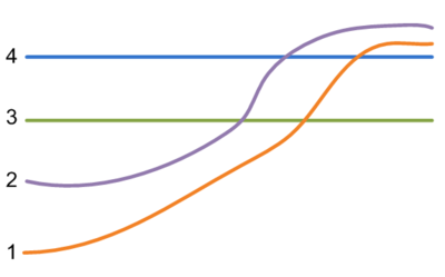
Horizons can be represented as rasters, one for each horizon ID. The rasters will typically be created by interpolating the borehole contact data for each horizon. When organized in a raster catalog, the rasters can be used to create GeoSection and GeoVolume features based on an attribute field containing the horizon ID. The figure on the right shows a schematic illustration of surfaces indexed with horizon IDs.
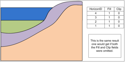
The tools that derive features from rasters include Fill and Clip fields to control the way the 3D model is constructed. The default value for Clip is "0", which indicates no clipping on a horizon. The default value for Fill is "1", which fills in between horizons to build GeoSection and GeoVolume features. Using the default options and running the tools on the data represented in the figure on the right gives the results shown in figure below.
The rasters used in creation of the raster catalog are often built from borehole contacts (points) which have been interpolated to rasters. Depending on the density of the points and the interpolation method used to build the rasters, there may be portions of the raster which do not accurately reflect the subsurface data. For example, the top horizon may come from actual measured land surface elevations, while the interpolated rasters for lower horizons may actually extend higher than the surface due to interpolation.
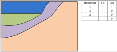
If a Clip field is used in a raster catalog containing horizon data, and the field value for a particular horizon is assigned to "1", then that horizon will be used as a clipping plane. Horizons beneath the clipping horizon that extend above the clipping horizon will be cut off. Consider the figure below, where the horizon with a HorizonID of "4" is assigned an attribute to clip. This would reflect the case where a horizon is used to represent measured elevations at the surface. The portions of the bottom two features that extend above the horizon with a horizon ID of "4" have been clipped.
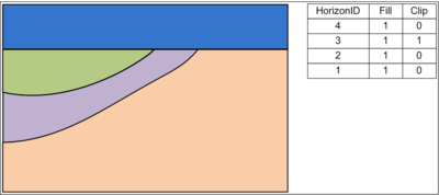
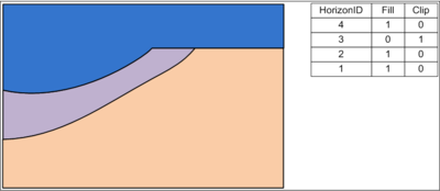
The clip option can also be used for horizons found in the middle of the subsurface data. This might be useful to model depositional strata located beneath the surface. An example of this can be found in the figure below, where the surface with HorizonID of "3" is used as a clipping surface.
The fill option, which is "1" by default, can be used to specify whether a horizon is filled in between adjacent horizons. A value of "1" is used in the Fill field to specify filling in between horizons, while a value of "0" turns off filling. If the fill option is not turned on, then no horizon is created for that horizon ID. Such a horizon will still be used to define the boundaries of the features created by the tools. This can be seen in the example shown in the final figure (below), where the surface represented by HorizonID "3" is disabled as a filling surface.
| [show] AHGW – Arc Hydro Groundwater Toolbox |
|---|
