GMS:FEMWATER Model Input: Difference between revisions
From XMS Wiki
Jump to navigationJump to search
| (41 intermediate revisions by 2 users not shown) | |||
| Line 4: | Line 4: | ||
==Titles== | ==Titles== | ||
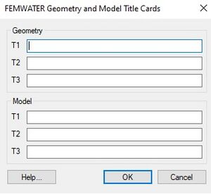
[[File:FEMWATERtitles.jpg|thumb|300 px|''FEMWATER Geomtery and Model Title Cards'' dialog]] | [[File:FEMWATERtitles.jpg|thumb|300 px|''FEMWATER Geomtery and Model Title Cards'' dialog]] | ||
The | The '''Titles''' command in the ''FEMWATER'' menu is used to enter two sets of titles. Each set contains three lines of text. The first set is written to the top of the geometry file when the simulation is saved. The second set is written to the top of the model file. | ||
==Run Options== | |||
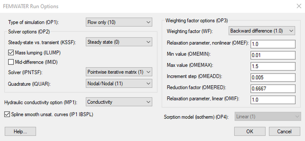
The ''FEMWATER Run Options'' dialog is used to set the simulation run parameters and to enter a set of general analysis options. | |||
*''Type of Simulation'' – Three options are available for designating the type of simulations to be performed by FEMWATER: | |||
**"Flow only" – This option is used to perform a steady state or transient flow simulation. | |||
**"Perform a transport simulation only" – For this case, a steady state or transient flow simulation must be performed prior to the transport simulation. The results of this simulation (velocity and moisture content) are then input to FEMWATER as a flow solution [[GMS:FEMWATER Initial Conditions|initial condition]]. | |||
**"Coupled flow and transport" – With a coupled flow and transport simulation, either density-dependent flow or density-independent flow can be simulated. This option is controlled by entering the appropriate parameters defining the relationship between concentration and density and concentration and viscosity. These parameters are entered in the ''Fluid Properties'' dialog. | |||
*''Steady State vs. Transient'' – FEMWATER can be run in either a steady state or transient mode. The steady state mode is only allowed when the ''Flow only'' option has been selected. | |||
*'''Units''' – The '''Units''' button brings up the [[GMS:Units|''Units'']] dialog. This dialog is used to enter the units for length, time, concentration, etc. for the simulation. GMS uses the selected unit options to display the appropriate units next to each input edit field in the other FEMWATER dialogs. | |||
*''Other Options'' – The remaining run options are described in the FEMWATER Reference Manual. In most cases, the default values are appropriate. | |||
[[File:FEMWATER RunOptions.png|thumb|none|600 px|The ''FEMWATER Run Options'' dialog]] | |||
==Iteration Parameters== | ==Iteration Parameters== | ||
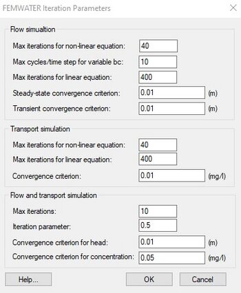
The ''FEMWATER Iteration Parameters'' dialog is used to enter the iteration parameters for each simulation type (flow only, transport only, coupled flow and transport). | |||
[[File:FEMWATERiteration.jpg|thumb|none|left|350 px|''FEMWATER Iteration Parameters'' dialog]] | [[File:FEMWATERiteration.jpg|thumb|none|left|350 px|''FEMWATER Iteration Parameters'' dialog]] | ||
==Particle Tracking Parameters== | ==Particle Tracking Parameters== | ||
The ''Particle Tracking'' dialog is used to edit parameters relating to how the particle tracking is carried out by FEMWATER during the transport phase. | [[File:FEMWATER ParticleTracking.png|thumb|240 px|The ''FEMWATER Particle Tracking'' dialog]] | ||
The ''FEMWATER Particle Tracking'' dialog is used to edit parameters relating to how the particle tracking is carried out by FEMWATER during the transport phase. | |||
FEMWATER particle tracking refers to the algorithm used by FEMWATER to do advective transport. In GMS versions 6.5 and earlier there was another type of particle tracking available which was similar to [[GMS:MODPATH|MODPATH]] but for FEMWATER flow solutions. That functionality is documented on the [[GMS:FEMWATER Particle Sets|FEMWATER Particle Sets]] page. | FEMWATER particle tracking refers to the algorithm used by FEMWATER to do advective transport. In GMS versions 6.5 and earlier there was another type of particle tracking available which was similar to [[GMS:MODPATH|MODPATH]] but for FEMWATER flow solutions. That functionality is documented on the [[GMS:FEMWATER Particle Sets|FEMWATER Particle Sets]] page. | ||
Page 32 of the FEMWATER manual describes the particle tracking used in advective transport. However the algorithm described is not actually used in the code. Instead a simpler adaptive | Page 32 of the FEMWATER manual describes the particle tracking used in advective transport. However the algorithm described is not actually used in the code. Instead a simpler adaptive time stepping algorithm is used. The parameter NXW is used as a "time step divisor" – backtracking begins by assuming a sub-time step, and every time backtracking fails, this sub-time step is divided by 2. NXW is used as an "Initial number of steps per time step" and the other parameters on the PT1 card are ignored. | ||
==Time Control Parameters== | ==Time Control Parameters== | ||
[[Image:time. | [[Image:time.png|thumb|left|380 px|Timeline of computational time steps defined using the ''Variable Time Step'' option and the ''XY Series Editor''.]] | ||
The ''Time Control'' dialog is used to enter the data used by FEMWATER to compute the computational time intervals. It is also used to define the reference time. The options in the dialog are as follows: | The ''FEMWATER Time Control'' dialog is used to enter the data used by FEMWATER to compute the computational time intervals. It is also used to define the reference time. The options in the dialog are as follows: | ||
====Time Steps==== | ====Time Steps==== | ||
There are two methods for defining the computational time steps: Constant time step and Variable time step. With the Constant time step method, the first time step is assumed to begin at time 0.0. A constant interval time is entered along with a maximum simulation time. For example, if a constant time step of 2.0 is defined along with a maximum simulation time of 10.0, six computational time steps will be defined at 0.0 (the initial condition), 2.0, 4.0, 6.0, 8.0 and 10.0. | There are two methods for defining the computational time steps: ''Constant time step'' and ''Variable time step''. With the ''Constant time step'' method, the first time step is assumed to begin at time 0.0. A constant interval time is entered along with a maximum simulation time. For example, if a constant time step of 2.0 is defined along with a maximum simulation time of 10.0, six computational time steps will be defined at 0.0 (the initial condition), 2.0, 4.0, 6.0, 8.0 and 10.0. | ||
The Variable time step option permits variable intervals between time steps. Selecting the Variable Times button brings up the XY Series Editor. The [[XY Series Editor|XY Series Editor]] has one column for entering times and another for entering time steps. In the time column, the absolute time for a computational time step should be entered. The time step corresponding to each time represents the interval to be used from one specified time to the next. | The ''Variable time step'' option permits variable intervals between time steps. Selecting the '''Variable Times''' button brings up the ''XY Series Editor''. The [[XY Series Editor|''XY Series Editor'']] has one column for entering times and another for entering time steps. In the time column, the absolute time for a computational time step should be entered. The time step corresponding to each time represents the interval to be used from one specified time to the next. | ||
A simple example of times and time steps defined in the XY Series Editor and the resulting computational time steps to be used by FEMWATER is shown below. In this case the maximum simulation time is equal to 48.0. | A simple example of times and time steps defined in the ''XY Series Editor'' and the resulting computational time steps to be used by FEMWATER is shown below. In this case the maximum simulation time is equal to 48.0. | ||
==Output Control== | ==Output Control== | ||
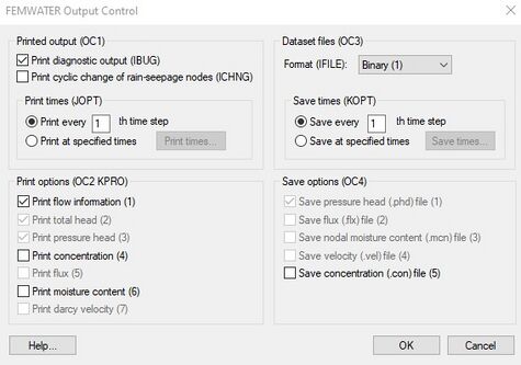
[[File:FEMWATEROutput.jpg|thumb|475 px|''FEMWATER Output Control'' dialog]] | [[File:FEMWATEROutput.jpg|thumb|475 px|''FEMWATER Output Control'' dialog]] | ||
The ''Output Control'' dialog is used to enter parameters defining what type of output will be printed or saved from FEMWATER. | The ''FEMWATER Output Control'' dialog is used to enter parameters defining what type of output will be printed or saved from FEMWATER. | ||
====Printed Output File==== | ====Printed Output File==== | ||
| Line 50: | Line 53: | ||
==Fluid Properties== | ==Fluid Properties== | ||
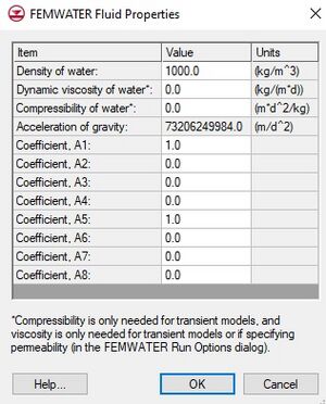
The | The '''Fluid Properties''' command in the ''FEMWATER'' menu brings up the ''FEMWATER Fluid Properties'' dialog. This dialog is used to specify the acceleration of gravity and the density, viscosity, and compressibility of the fluid. | ||
The '''Edit Values''' button brings up the ''FEMWATER Fluid Coefficients'' dialog. This button is undimmed when transport is being analyzed as part of the simulation. | The '''Edit Values''' button brings up the ''FEMWATER Fluid Coefficients'' dialog. This button is undimmed when transport is being analyzed as part of the simulation. | ||
| Line 63: | Line 66: | ||
'''Hydraulic Conductivity Tensor''' | '''Hydraulic Conductivity Tensor''' | ||
{| class="wikitable" border="1" | :{| class="wikitable" border="1" | ||
|- | |- | ||
| Kxx | | Kxx | ||
| Line 78: | Line 81: | ||
|} | |} | ||
*''Moisture Content, Relative Conductivity, Water Capacity curves'' – These unsaturated zone curves must be defined for each material. The curves can be defined using either the XY Series Editor or the Curve Generator (discussed below). The Curve Generator is accessed via the '''Generate Unsat Curves''' button in the bottom of the dialog. When that button is selected, the curves that are generated will be associated with the active material, or the material in the spreadsheet row that currently has the focus. | *''Moisture Content, Relative Conductivity, Water Capacity curves'' – These unsaturated zone curves must be defined for each material. The curves can be defined using either the ''XY Series Editor'' or the ''Curve Generator'' (discussed below). The ''Curve Generator'' is accessed via the '''Generate Unsat Curves''' button in the bottom of the dialog. When that button is selected, the curves that are generated will be associated with the active material, or the material in the spreadsheet row that currently has the focus. | ||
=== Curve Generator === | === Curve Generator === | ||
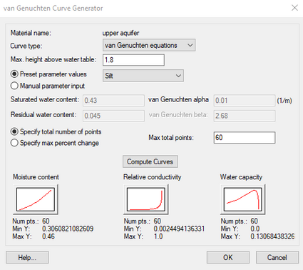
[[File:FEMWATER CurveGenerator.png|thumb|425 px|The FEMWATER ''Curve Generator'' dialog]] | |||
In most cases, the simplest way to generate a set of pressure head curves for the unsaturated zone is to use the ''Curve Generator''. The '''Generate Unsat Curves''' button brings up the ''Curve Generator'' dialog. This dialog is used to automatically generate a set of unsaturated zone curves using the van Genuchten equations described in the FEMWATER Reference Manual. The items in the top of the dialog are used to select the curve type ('linear front' or 'van Genuchten equation') and the max height of capillary rise above the water table. Two methods are available for entering the Van Genuchten parameters: (1) selecting the ''Manual parameter input'' option and enter the values directly, or (2) selecting the ''Preset parameter values'' option and choose from a list of pre-defined soil types. | |||
Once the parameters are defined the '''Compute Curves''' button can be used to generate a set of curves. The curves are displayed in the bottom of the dialog. New values can be entered and the process can be repeated until a satisfactory result is obtained. When the '''OK''' button is selected, the active curves are assigned to the current material. | |||
Once the parameters are defined the '''Compute Curves''' button can be used to generate a set of curves. The curves are displayed in the bottom of the dialog. New values can be entered and the process can be repeated until a satisfactory result is obtained. When the OK button is selected, the active curves are assigned to the current material. | |||
Each of the unsaturated zone curves is a piece-wise linear curve defined by a sequence of points. The number of points in each curve is either specified by the user or determined automatically by specifying a ''Max percent change''. If the '''max percent change''' option is used, a new point is added to the curve each time the parameter changes by the Max percent value. | Each of the unsaturated zone curves is a piece-wise linear curve defined by a sequence of points. The number of points in each curve is either specified by the user or determined automatically by specifying a ''Max percent change''. If the '''max percent change''' option is used, a new point is added to the curve each time the parameter changes by the Max percent value. | ||
| Line 90: | Line 93: | ||
Note that the effective porosity for each material is defined from the pressure head vs. moisture content curve. The value at p = 0 is taken from the curve and is written to the model file as part of the MP2 card. | Note that the effective porosity for each material is defined from the pressure head vs. moisture content curve. The value at p = 0 is taken from the curve and is written to the model file as part of the MP2 card. | ||
Note also that GMS assumes that the van Genuchten 'alpha' value is entered in units consistent with the current model units. GMS displays the current model units next to the input field to help the user remember this. | |||
{{Navbox GMS}} | {{Navbox GMS}} | ||
[[Category:FEMWATER]] | [[Category:FEMWATER|Model]] | ||
[[Category:FEMWATER Dialogs|Model]] | |||
[[Category:Needs Update]] | |||
