User:Jmonson/WMS:1D-HYD Cross Section Coverage Type: Difference between revisions
Aconcepcion (talk | contribs) No edit summary |
|||
| (11 intermediate revisions by 2 users not shown) | |||
| Line 1: | Line 1: | ||
__NOINDEX__ | __NOINDEX__ | ||
{{Version WMS 11.0}} | |||
[[Image:1D-CenterlineExample.png|thumb|right|Example cross sections with a centerline and bank arcs.]] | [[Image:1D-CenterlineExample.png|thumb|right|Example cross sections with a centerline and bank arcs.]] | ||
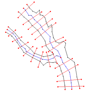
The '''1D-Hydraulic Cross Section coverage''' is used to identify the cross section stations in the hydraulic model, and can also be used to automatically cut a cross section from an underlying digital terrain model. This coverage is used in conjunction with the cross sections and digital terrain model in order to determine the thalweg position, or lowest point in the cross section (from the centerline arc), and the left and right bank points (from the bank arcs). | The '''1D-Hydraulic Cross Section coverage''' is used to identify the cross section stations in the hydraulic model, and can also be used to automatically cut a cross section from an underlying digital terrain model. This coverage is used in conjunction with the cross sections and digital terrain model in order to determine the thalweg position, or lowest point in the cross section (from the centerline arc), and the left and right bank points (from the bank arcs). | ||
| Line 5: | Line 6: | ||
There are several attributes of a cross section feature arc, including the the cross-section itself and other parameters that define its topology in the model. These include a ''Cross Section ID'' (internally assigned), the ''Reach Name'' (inherited from the centerline arc it intersects), the ''Station'' (inherited from the centerline), and any specific model attributes. | There are several attributes of a cross section feature arc, including the the cross-section itself and other parameters that define its topology in the model. These include a ''Cross Section ID'' (internally assigned), the ''Reach Name'' (inherited from the centerline arc it intersects), the ''Station'' (inherited from the centerline), and any specific model attributes. | ||
A cross section profile is assigned automatically when | Cross section geometry is stored in text database files, and extracted cross sections are saved to a new (or existing) database file. One way to create cross sections is to extract them from digital terrain models, but this is not the only method. They can also be created by importing them from spreadsheet data and by entering them manually. | ||
A cross section profile is assigned automatically when creating the cross sections, or can be assigned manually (imported from a file or entered directly) using the [[#Editing Cross Sections|cross section editor]]. | |||
==Cross Section Databases== | |||
[[File:WMS - Cross section database example.png|thumb|right|Example of a cross section database file.]] | |||
Cross section databases are plain text files that contain information about points along each cross section. Databases can be manually edited or edited using the [[#Cross Section Attributes Dialog|''Cross Section Attributes'' dialog]]. It is also possible to import a cross section database using the ''File'' | '''[[WMS:File Menu#Open|Open...]]''', or by clicking the '''Import''' button in the [[#Managing Cross Sections|''Manage Cross Sections'']] or [[#Assign Cross Section Dialog|''Assign Cross Section'']] dialogs. | |||
The following parts comprise each entry: | |||
*The section of the channel (e.g., "Channel Section 3") | |||
*A "D" column indicating distance from the right channel bank (as if looking downstream) | |||
*A "Z" column indicating the elevation of the channel bed at that point in the cross section profile | |||
{{-}} | |||
==River Cross Section Attributes Dialog== | ==River Cross Section Attributes Dialog== | ||
[[File:WMS - River Cross Section Attributes dialog.png|thumb|right|275 px|''River Cross Section Attributes'' dialog.]] | [[File:WMS - River Cross Section Attributes dialog.png|thumb|right|275 px|''River Cross Section Attributes'' dialog.]] | ||
The ''River Cross Section Attributes'' dialog is accessed by using the '''Select Feature Arc''' [[File:WMS SelectArcTool.svg|16px]] tool to: | The ''River Cross Section Attributes'' dialog is accessed by selecting the 1D-Hydraulic cross section coverage containing the cross section arcs and using the '''Select Feature Arc''' [[File:WMS SelectArcTool.svg|16px]] tool to: | ||
*Double-click on a cross section arc, | *Double-click on a cross section arc, | ||
*Right-click on a cross section arc and | *Right-click on a cross section arc and select '''Attributes...''' from the pop-up menu, or | ||
*Select the cross section arc and | *Select the cross section arc and select ''Feature Objects'' | '''Attributes'''. | ||
There are three sections within this dialog: | There are three sections within this dialog: | ||
| Line 28: | Line 42: | ||
**Check the ''Bridge/culvert'' box to indicate the cross section is a bridge/culvert. | **Check the ''Bridge/culvert'' box to indicate the cross section is a bridge/culvert. | ||
**If the ''Bridge/culvert'' box is turned on, the '''Options...''' button becomes available. Clicking it brings up the [[#Bridge/Culvert Cross Section Attributes Dialog|''Bridge/Culvert Cross Section Attributes'' dialog]]. | **If the ''Bridge/culvert'' box is turned on, the '''Options...''' button becomes available. Clicking it brings up the [[#Bridge/Culvert Cross Section Attributes Dialog|''Bridge/Culvert Cross Section Attributes'' dialog]]. | ||
{{-}} | {{-}} | ||
| Line 40: | Line 53: | ||
**The type of cross section can be selected from the ''Cross Section Type'' drop-down. There are two options: "Bridge" or "Culvert". | **The type of cross section can be selected from the ''Cross Section Type'' drop-down. There are two options: "Bridge" or "Culvert". | ||
**Clicking the '''Edit Parameters''' button brings up the [[#Bridge/Culvert Parameters Dialog|''Bridge/Culvert Parameters'' dialog]]. | **Clicking the '''Edit Parameters''' button brings up the [[#Bridge/Culvert Parameters Dialog|''Bridge/Culvert Parameters'' dialog]]. | ||
{{-}} | {{-}} | ||
| Line 59: | Line 71: | ||
Enter the correct amounts for each option in the ''Value'' column, making note of the measurement in the ''Units'' column to ensure accuracy. | Enter the correct amounts for each option in the ''Value'' column, making note of the measurement in the ''Units'' column to ensure accuracy. | ||
{{-}} | |||
==Assign Cross Section Dialog== | |||
[[File:WMS - Assign Cross Section dialog.png|thumb|right|''Assign Cross Section'' dialog]] | |||
The ''Assign Cross Section'' dialog is accessed via the '''Assign Cross Section''' button in the [[#River Cross Section Attributes Dialog|''River Cross Section Attributes'' dialog]]. There are two sections in this dialog: | |||
*''Cross Section Database'' | |||
**The drop-down at the top of this section allows selecting which database to use. There may only be one item in the list. | |||
**The '''New Database''' button creates a new database. | |||
**The '''Delete Database''' button deletes the currently-selected database. '''NOTE:''' Clicking this button immediately deletes the selected database, without asking for confirmation. Be cautious when using this button. | |||
**The drop-down to the left of the '''Import...''' button allows two selections: | |||
***"CSDB file (*.wms; *.sms; *.h5; *.idx)" | |||
***"HEC-RAS / HEC-2 (*.g*; *.dat)" | |||
**The '''Import...''' button brings up an ''Open'' dialog where a file of the type selected from the above drop-down can be imported. | |||
**The '''Export''' button brings up a ''Select a database name'' dialog where the current database can be exported as an XMDF H5 file. | |||
**The '''Database → Cov''' button creates a new coverage based on the selected database. | |||
**The '''Cov → Ln Props''' button converts material properties from an area property coverage to line properties on the cross section(s). | |||
**The '''Database → DTM''' button creates a new TIN based on the elevation points in the selected cross section database. | |||
**The '''Topo ID''' button button brings up the [[#CsDb Topo Management Dialog|''CsDb Topo Management'' dialog]]. | |||
**The '''Line Prop Types''' button brings up the [[#Line Property Types Dialog|''Line Property Types'' dialog]]. | |||
**The '''Pt Prop Types''' button brings up the [[#Point Property Types Dialog|''Point Property Types'' dialog]]. | |||
*''Cross Section'' - At the top of this section is a count of the ''Number of Cross Sections''. Below that is a table of each of the reaches, stations, and the cross section assignments. There are four buttons to the right of the table: | |||
**'''New''' - Creates a new entry in the table. | |||
**'''Edit''' - Edit the selected entry by bringing up the [[#Cross Section Attributes Dialog|''Cross Section Attributes'' dialog]]. | |||
**'''Copy''' - Make a duplicate of the selected entry. | |||
**'''Delete''' - Delete the selected entry. '''NOTE:''' Clicking this button immediately deletes the selected entry, without asking for confirmation. Be cautious when using this button. | |||
Below the table is a plot showing the selected cross section. | |||
'''NOTE:''' Clicking the '''Cancel''' button will not cancel database changes, but it will cancel assignment changes. | |||
{{-}} | {{-}} | ||
==Assign Cross Section Dialog== | ===CsDb Topo Management Dialog=== | ||
[[File:WMS - Assign Cross Section dialog.png|thumb| | [[File:WMS - CsDb Topo Management dialog.png|thumb|right|''CsDb Topo Management'' dialog]] | ||
The ''CsDb Topo Management'' dialog is accessed via the '''Topo ID''' button in the [[#Assign Cross Section Dialog|''Assign Cross Section'' dialog]]. It displays a table of defined topo IDs in the database. | |||
*Above the table is a count of the ''Total Topo IDs''. | |||
*The table of IDs has columns for ''Topo ID'' and ''Description''. | |||
*Use the '''Add''' button to create a new topo ID entry in the table. | |||
*Use the '''Delete''' button to delete the selected topo ID entry from the table. | |||
{{-}} | |||
===Line Property Types Dialog=== | |||
[[File:WMS - Line Property Types dialog.png|thumb|right|''Line Property Types'' dialog]] | |||
The ''Line Property Types'' dialog is accessed via the '''Topo ID''' button in the [[#Assign Cross Section Dialog|''Assign Cross Section'' dialog]]. The ''Line Property Types'' dialog displays a table of defined material types in the database. The following columns are defined in the table: | |||
*''Name'' - The name of the line property type. This field can be edited. | |||
*''Description'' - A brief description of the line property type. This field can be edited. | |||
*''Data Type'' - Select one of four options from the drop-down: | |||
**"Float" | |||
**"Integer" | |||
**"Materials" | |||
**"Enumerated" | |||
*''Default'' - This value type changes depending on the ''Data Type'' selected from the drop-down: | |||
**"Float" - Enter a decimal value. | |||
**"Integer" - Enter an integer value. | |||
**"Materials" - Select from the values listed in the [[#Property Categories Dialog|''Property Categories'' dialog]]. | |||
**"Enumerated" - Select from the values listed in the [[#Property Categories Dialog|''Property Categories'' dialog]]. | |||
*''Category Items'' - The '''Define...''' button is accessible only when "Enumerated" is selected from the ''Data Type'' drop-down. Clicking the '''Define...''' button brings up the [[#Property Categories Dialog|''Property Categories'' dialog]]. | |||
New types can be created using the '''New''' button. Entries can be deleted using the '''Delete''' button. | |||
====Property Categories Dialog==== | |||
[[File:WMS - Property Categories dialog.png|thumb|right|''Property Categories'' dialog]] | |||
The ''Property Categories'' dialog is accessed via the '''Define...''' button in the ''Category Items'' column in the [[#Line Property Types Dialog|''Line Property Types'' dialog]]. It is accessible only when "Enumerated" is selected from the ''Data Type'' drop-down. It displays a list of defined property categories in the database. The following categories appear in the Items section by default: | |||
*"Disable" | |||
*"River" | |||
*"Agriculture" | |||
*"Urban" | |||
*"Brushland" | |||
*"Bare" | |||
New categories can be added by clicking the '''New''' button, double-clicking on the "New Item" entry, and entering the desired name. Categories can be deleted from the list by selecting the category and clicking '''Delete'''. | |||
{{-}} | |||
===Point Property Types Dialog=== | |||
[[File:WMS - Point Property Types dialog.png|thumb|right|''Point Property Types'' dialog]] | |||
The ''Point Property Types'' dialog is accessed via the '''Pt Prop Types''' button in the [[#Assign Cross Section Dialog|''Assign Cross Section'' dialog]]. It displays a table of defined point types in the database. The columns are: | |||
*''Name'' - The name of the type. The names for user-created types can be edited. | |||
*''Description'' - A brief description of the type. The description for user-created types can be edited. | |||
*''Exclusive'' - If this box is checked, there can only be one entry of that type on a cross section. See [[#Point Properties|below]] for more details. | |||
New point property types can be created by clicking '''New''' and editing the ''Name'', ''Description'', and ''Exclusive'' columns for the new entry. Though other properties can be defined, they are not mapped or saved to hydraulic models from within WMS. The '''Delete''' button can be used to delete user-created types. | |||
{{-}} | |||
==Editing Cross Sections== | ==Editing Cross Sections== | ||
After creating a cross section, additional refinement editing may need to be completed prior to using them for hydraulic modeling. | |||
Cross sections can be edited in the following ways: | |||
*Click the '''Edit''' button in the [[#Assign Cross Section Dialog|''Assign Cross Section'' dialog]]. | |||
*Open a cross section database for editing (or create a new database) using the [[#Managing Cross Sections|'''Manage Cross Sections''']] command. | |||
===Cross Section Attributes Dialog=== | |||
[[File:WMS - Cross Section Attributes dialog.png|thumb|right|''Cross Section Attributes'' dialog.]] | |||
The ''Cross Section Attributes'' dialog is accessed by clicking the '''Edit''' button in the [[#Assign Cross Section Dialog|''Assign Cross Section'' dialog]] or in the ''Manage Cross Sections'' dialog. This dialog allows cross section attributes to be modified as project needs dictate. | |||
At the top of the dialog is a plot of the selected cross section. A toolbar is visible when the ''[[#Editing Geometry|Geom Edit]]'' tab is selected. | |||
[[ | The following tabs are located in the bottom right section of the dialog: | ||
*''[[#Editing Geometry|Geom Edit]]'' - This tab is displayed by default when the ''Cross Section Attributes'' dialog opens. | |||
*''[[#Geo-Referencing|Geo Ref]]'' | |||
*''[[#Line Properties|Line Props]]'' | |||
*''[[#Point Properties|Point Props]]'' | |||
*''[[#Merging|Merge]]'' | |||
*''[[#Filtering|Filter]]'' | |||
At the bottom left of the dialog are the following items: | |||
*''CS Name'' - The name of the selected cross section. This field is editable and can be left blank. | |||
*''Reach'' - The name of the reach on which the cross section is found. This field is not editable. | |||
*''Station'' - The elevation of the station corresponding to the cross section. | |||
*''Topo'' - A drop-down list all of topographic datasets in the project. The name of the topographic data used to extract the cross section (if applicable) will be selected. | |||
*''Num. of points'' - The number of points on the cross section arc. | |||
*''Num of point properties'' - The number of defined point properties. | |||
*''Num of line properties'' - The number of defined line properties. | |||
*''Note'' - A note field. This field is editable and can be left blank. | |||
Not all of these attributes are critical for the development of a hydraulic model, but they are useful in managing the cross section within a database. | |||
The | The following tools are found at the bottom left of the plot except when the ''[[#Geo-Referencing|Geo Ref]]'' tab is selected: | ||
*[[File:Create Points Tool.svg|16px]] '''Add Point''' - Adds a new point to the plot. | |||
*[[File:Select Point Tool.svg|16px]] '''Select Point''' - Selects a point on the plot. | |||
*[[File:Select Breakpoint Tool.svg|16px]] '''Select Breakpoint''' - Selects a breakpoint on the plot. | |||
*[[File:Insert Breakpoint Tool.svg|16px]] '''Insert Breakpoint''' - Inserts a breakpoint into the plot. | |||
*[[File:Select Line Property Tool.svg|16px]] '''Select Line Property''' - Selects a line property. | |||
*[[File:Zoom Tool Icon.svg|16px]] '''Zoom Tool''' - Zoom in or out on a specific location in the plot. | |||
=== | ====Editing Geometry==== | ||
The ''Geom Edit'' tab allows cross section points to be added and the values of those points to be edited. ''XY'' values are available when the actual 3D position of each point on the cross section is known. The more traditional ''D-Z'' pairs define the distance from the starting point and a corresponding elevation. | |||
The options on the ''Geom Edit'' tab are: | |||
*''Display'' - The ''XY'' and ''D'' columns in the spreadsheet can be turned on or off. | |||
*The spreadsheet displays columns containing values for ''X'', ''Y'', ''D'', and ''Z''. | |||
*The '''Add''' button adds a new point to the cross section arc and a corresponding row to the spreadsheet. | |||
*The '''Delete Pt''' button removes the selected point from the cross section arc, also removing the corresponding row from the spreadsheet. | |||
*The '''Sort''' button sorts the spreadsheet in ascending order based on the value in the ''X'' column. | |||
The ''Nudge'' section has directional buttons that move the selected point '''Up''', '''Down''', '''Left''', or '''Right''' based on the values entered in the ''Step Z'' and ''Step D'' fields. | |||
====Geo-Referencing==== | |||
[[File:WMS - Cross Section Attributes dialog - Geo Ref tab.png|thumb|right|The ''Geo Ref'' tab.]] | |||
The ''Geo Ref'' tab has a ''Geo-Reference Method'' drop-down with the following options: | |||
*"No Georeferencing" | |||
*"Use one point and angle" - Enter ''X'', ''Y'', and ''D'' values in the ''Point'' section, an ''Angle'', and then click '''Apply'''. Use this method if the centerline location is known and some angle relative to it needs to be defined | |||
*"Use two points" - Enter ''X'', ''Y'', and ''D'' values in both the ''Primary Point'' and ''Secondary Point'' sections, then click '''Apply'''. These points are the coordinates for the beginning and ending locations along the defined cross section. | |||
*"All points specified" - Extracted cross sections will be of this type. | |||
Geo-referencing information provides the spatial (''xy'') location of the cross section and included geometry. This information is inherent in the 3D coordinates when extracting cross sections from a digital terrain model. However, if the cross section geometry is taken from a survey, the actual ''xyz'' coordinates of the points may not be known. In order to use the data within WMS for floodplain delineation, a proper geo-reference must be provided. | |||
{{-}} | |||
The | ====Line Properties==== | ||
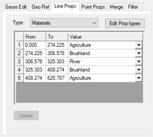
[[File:WMS - Cross Section Attributes dialog - Line Props tab.png|thumb|right|The ''Line Props'' tab.]] | |||
The ''Line Props'' tab allows for the defining of segments of material properties along the cross section. If an area property coverage was used during extraction from a digital terrain model, these properties are automatically marked and defined. They can be manually adjusted and managed from this tab. | |||
The following items are found here: | |||
*''Type'' - A drop-down to select the type of line property. "Materials" is the default and is often the only option. | |||
*The '''Edit Prop types''' button opens the [[#Line Property Types Dialog|''Line Property Types'' dialog]]. | |||
*The '''Delete''' button is used to delete the selected entry from the spreadsheet. | |||
The spreadsheet has three columns: | |||
*''From'' - Defines the beginning location of the segment. This field is editable. | |||
*''To'' - Defines the ending location of the segment. This field is editable. | |||
*''Value'' - Defines the material type. If the material type is incorrect, a different type can be selected from the drop-down here. | |||
{{-}} | |||
=== | ====Point Properties==== | ||
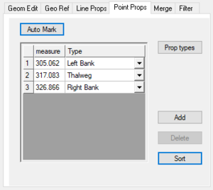
[[File:WMS - Cross Section Attributes dialog - Point Props tab.png|thumb|right|The ''Point Props'' tab.]] | |||
The ''Point Props'' tab allows the point properties on the cross section to be edited. By default, these properties include "Thalweg" (the lowest elevation), "Left Bank", and "Right Bank" (determined by appropriate breaks in elevation/slope). When using a centerline and bank line arcs from a 1D Hydraulic Centerline coverage during extraction, these points are automatically marked. The '''Auto Mark''' button allows this process to be initiated manually. | |||
The buttons along the right side are: | |||
*'''Prop types''' - Opens the [[#Point Property Types Dialog|''Point Property Types'' dialog]]. | |||
*'''Add''' - Adds a new entry to the spreadsheet. '''NOTE:''' When adding new entries, be aware that some point property types are exclusive, meaning only one can exist per cross section. | |||
*'''Delete''' - Deletes the selected entry from the spreadsheet. | |||
*'''Sort''' - Sorts the entries in the spreadsheet in ascending order based on the ''measure'' column. | |||
== | The ''measure'' column lists the distance along the cross section to the point. The ''Type'' column contains a drop-down allowing the point property type to be selected. | ||
{{-}} | |||
====Merging==== | |||
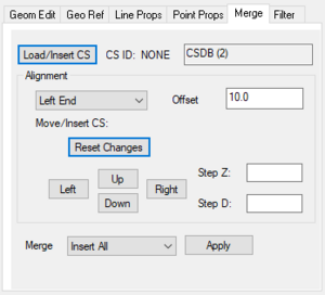
[[File:WMS - Cross Section Attributes dialog - Merge tab.png|thumb|right|The ''Merge'' tab.]] | |||
The ''Merge'' tab allows two cross sections to be merged. For example, if a terrain model does not contain enough detail to define the cross section of the river, a more detailed survey cross section could be inserted and merged using the tools on this tab. | |||
'''NOTE:''' When merging cross sections, the new cross section must be created in a new cross section database before being merged with an existing cross section database. | |||
The ''' | The '''Load/Insert CS''' button brings up the [[#Assign Cross Section Dialog|''Assign Cross Section'' dialog]]. Once the desired cross section has been imported and/or selected, click '''OK''' to return. The database will be displayed to the right of the ''CS ID'' to the right of the '''Load/Insert CS''' button. | ||
The ''Alignment'' section allows the selection of where the two cross sections are aligned: | |||
*"Left End" | |||
*"Left Bank" | |||
*"Thalweg" | |||
*"Right Bank" | |||
*"Right End" | |||
An ''Offset'' can be specified. The offset uses the units set for the project. The imported cross section can be nudged '''Up''', '''Down''', '''Left''', or '''Right''' based on the values entered in the ''Step Z'' and ''Step D'' fields. The '''Reset Changes''' button resets the nudging. | |||
Below the ''Alignment'' section, the ''Merge'' drop-down offers the following options: | |||
*"Insert All" | |||
*"Insert Channel" | |||
*"Blend Banks" | |||
*"Blend All" | |||
Clicking the '''Apply''' button applies any changes made and updates cross section. | |||
=== | ====Filtering==== | ||
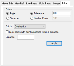
[[File:WMS - Cross Section Attributes dialog - Filter tab.png|thumb|right|The ''Filter'' tab.]] | |||
The ''Filter'' tab allows specifying rules for filtering "insignificant" points along the cross section in the case where there are more points defining the cross section than are necessary (or that the hydraulic model is capable of processing). This can be particularly important when extracting cross sections from a dense digital terrain model. | |||
The ''Criteria'' section allows selecting from the following options: | |||
*''Angle'' or ''Distance'' | |||
*''Tolerance'' or ''Number Points'' | |||
The ''Points'' drop-down contains the following options: | |||
*"All" | |||
*"Channel" | |||
*"Overbanks" | |||
Turning on the ''Lock points with point properties within a distance'' option allows a ''Distance'' to be set. Clicking the '''Apply''' button applies any changes made. | |||
{{-}} | |||
The ''' | ==Extracting Cross Sections== | ||
[[Image:ExtractCrossSections.jpg|thumb|right|''Extract Cross Sections'' dialog.]] | |||
The '''Extract Cross Sections''' command in the ''River Tools'' menu brings up the ''Extract Cross Sections'' dialog. When extracting cross sections they are saved to a new (or existing) database file. This database was the basis for the development of the cross section data in the ArcHydro data model. Cross sections in the database can be used for the development of hydraulic models such as [[WMS:HEC-RAS|HEC-RAS]]. | |||
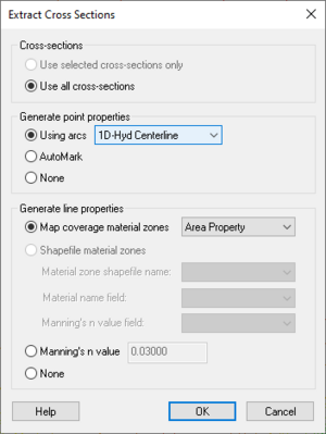
The ''Extract Cross Sections'' dialog uses the cross section arcs and a digital terrain model (either a TIN or a DEM) to extract the elevations at vertices of the feature arc cross sections, or at the intersection points with the triangles. There are three sections in this dialog: | |||
;''Cross sections'' | |||
:Cross sections for individual arcs may be extracted by selecting the arc(s) before choosing the '''Extract Cross Sections''' command. If no cross sections are selected, then only the ''Use all cross sections'' option is available. | |||
;''Generate point properties'' | |||
:Point properties (thalweg, left bank, right bank) can be defined from a 1D-Hydraulic centerline coverage, or by AutoMark. The ''AutoMark'' option examines the elevations of the extracted cross sections and infers the thalweg (low point) and the left and right bank points (change of slope) automatically. Selecting ''None'' means no point properties will be generated. | |||
;''Generate line properties'' | |||
:Selecting ''Material zones'' determines the line properties from the area property coverage selected in the drop-down by intersecting the cross section arcs with the area property polygons and marking them in the cross section database. Selecting ''Manning's n value'' generates the line properties based on the Manning's ''n'' value entered. Selecting ''None'' means no line properties will be generated. | |||
When '''OK''' is clicked, a popup will ask whether to extract the cross sections from a DEM or a TIN. | |||
The ''Cross Section | WMS stores all of the cross section information in a text database file. The cross section database can be edited independently using the [[#Editing Cross Sections|'''Cross Section Attributes''' dialog]]. Extracting cross sections with feature arcs is only way to generate cross section information. They also can be imported from spreadsheet files (cut and paste), or entered manually. | ||
'''NOTE:''' When merging cross sections, the new cross section must be created in a new cross section database before being merged with an existing cross section database. | |||
==Managing Cross Sections== | |||
[[File:WMS - Manage Cross Sections dialog.png|thumb|right|The ''Manage Cross Sections'' dialog.]] | |||
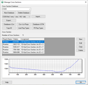
The ''Manage Cross Sections'' dialog can be accessed by selecting [[WMS:River Tools|''River Tools'']] | '''Manage Cross Sections...'''. This dialog is similar to the ''Assign Cross Section'' dialog, and all of the commands are [[#Assign Cross Section Dialog|described there]]. | |||
{{-}} | |||
==Related Topics== | ==Related Topics== | ||
| Line 156: | Line 317: | ||
* [[WMS:Interpolating Hydraulic Model Results|Interpolation of Results]] | * [[WMS:Interpolating Hydraulic Model Results|Interpolation of Results]] | ||
* [[WMS:River Tools|Hydraulic Modeling]] | * [[WMS:River Tools|Hydraulic Modeling]] | ||
{{WMSMain}} | {{WMSMain}} | ||
Latest revision as of 19:29, 14 June 2018
| This contains information about future functionality available starting at WMS version 11.0. The content may not apply to other versions. |
The 1D-Hydraulic Cross Section coverage is used to identify the cross section stations in the hydraulic model, and can also be used to automatically cut a cross section from an underlying digital terrain model. This coverage is used in conjunction with the cross sections and digital terrain model in order to determine the thalweg position, or lowest point in the cross section (from the centerline arc), and the left and right bank points (from the bank arcs).
There are several attributes of a cross section feature arc, including the the cross-section itself and other parameters that define its topology in the model. These include a Cross Section ID (internally assigned), the Reach Name (inherited from the centerline arc it intersects), the Station (inherited from the centerline), and any specific model attributes.
Cross section geometry is stored in text database files, and extracted cross sections are saved to a new (or existing) database file. One way to create cross sections is to extract them from digital terrain models, but this is not the only method. They can also be created by importing them from spreadsheet data and by entering them manually.
A cross section profile is assigned automatically when creating the cross sections, or can be assigned manually (imported from a file or entered directly) using the cross section editor.
Cross Section Databases
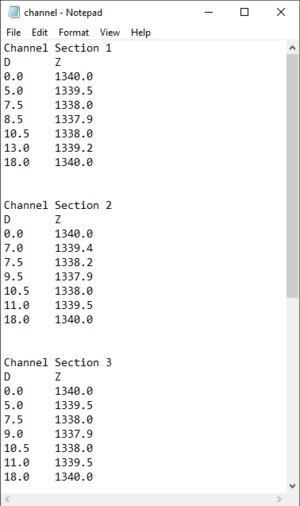
Cross section databases are plain text files that contain information about points along each cross section. Databases can be manually edited or edited using the Cross Section Attributes dialog. It is also possible to import a cross section database using the File | Open..., or by clicking the Import button in the Manage Cross Sections or Assign Cross Section dialogs.
The following parts comprise each entry:
- The section of the channel (e.g., "Channel Section 3")
- A "D" column indicating distance from the right channel bank (as if looking downstream)
- A "Z" column indicating the elevation of the channel bed at that point in the cross section profile
River Cross Section Attributes Dialog
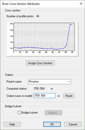
The River Cross Section Attributes dialog is accessed by selecting the 1D-Hydraulic cross section coverage containing the cross section arcs and using the Select Feature Arc ![]() tool to:
tool to:
- Double-click on a cross section arc,
- Right-click on a cross section arc and select Attributes... from the pop-up menu, or
- Select the cross section arc and select Feature Objects | Attributes.
There are three sections within this dialog:
- Cross section
- Displays the Number of profile points on the selected cross section arc.
- Displays a plot for the selected cross section arc.
- The Assign Cross Section button. Clicking this brings up the Assign Cross Section dialog.
- Station
- A Reach name drop-down that allows the desired reach name to be selected.
- The elevation of the Computed station.
- The elevation of the Station (user or model).
- A Reset button to reset the Station (user or model) back to the default elevation.
- Bridge/culvert
- Check the Bridge/culvert box to indicate the cross section is a bridge/culvert.
- If the Bridge/culvert box is turned on, the Options... button becomes available. Clicking it brings up the Bridge/Culvert Cross Section Attributes dialog.
Bridge/Culvert Cross Section Attributes Dialog
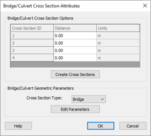
The Bridge/Culvert Cross Section Attributes dialog is accessed via the Options... button in the River Cross Section Attributes dialog. There are two sections within this dialog:
- Bridge/Culvert Cross Section Options
- This section contains a spreadsheet listing the Cross Section ID, Distance, and Units for each cross section arc.
- Clicking the Create Cross Sections button creates the cross sections listed in the spreadsheet.
- Bridge/Culvert Geometric Parameters
- The type of cross section can be selected from the Cross Section Type drop-down. There are two options: "Bridge" or "Culvert".
- Clicking the Edit Parameters button brings up the Bridge/Culvert Parameters dialog.
Bridge/Culvert Parameters Dialog
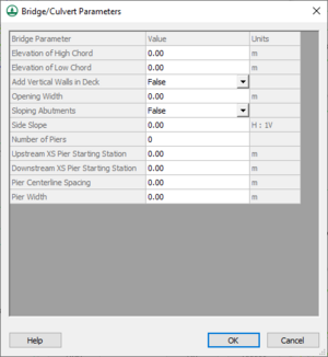
The Bridge/Culvert Parameters dialog is accessed via the Edit Parameters button in the Bridge/Culvert Cross Section Attributes dialog. The following options can be set in the spreadsheet:
- Elevation of High Chord
- Elevation of Low Chord
- Add Vertical Walls in Deck: Can be set to "True" or "False" using the drop-down in the Value column.
- Opening Width
- Sloping Abutments: Can be set to "True" or "False" using the drop-down in the Value column.
- Side Slope
- Number of Piers
- Upstream XS Pier Starting Station
- Downstream XS Pier Starting Station
- Pier Centerline Spacing
- Pier Width
Enter the correct amounts for each option in the Value column, making note of the measurement in the Units column to ensure accuracy.
Assign Cross Section Dialog
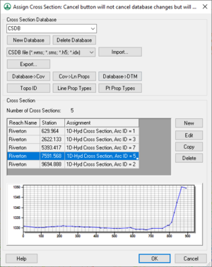
The Assign Cross Section dialog is accessed via the Assign Cross Section button in the River Cross Section Attributes dialog. There are two sections in this dialog:
- Cross Section Database
- The drop-down at the top of this section allows selecting which database to use. There may only be one item in the list.
- The New Database button creates a new database.
- The Delete Database button deletes the currently-selected database. NOTE: Clicking this button immediately deletes the selected database, without asking for confirmation. Be cautious when using this button.
- The drop-down to the left of the Import... button allows two selections:
- "CSDB file (*.wms; *.sms; *.h5; *.idx)"
- "HEC-RAS / HEC-2 (*.g*; *.dat)"
- The Import... button brings up an Open dialog where a file of the type selected from the above drop-down can be imported.
- The Export button brings up a Select a database name dialog where the current database can be exported as an XMDF H5 file.
- The Database → Cov button creates a new coverage based on the selected database.
- The Cov → Ln Props button converts material properties from an area property coverage to line properties on the cross section(s).
- The Database → DTM button creates a new TIN based on the elevation points in the selected cross section database.
- The Topo ID button button brings up the CsDb Topo Management dialog.
- The Line Prop Types button brings up the Line Property Types dialog.
- The Pt Prop Types button brings up the Point Property Types dialog.
- Cross Section - At the top of this section is a count of the Number of Cross Sections. Below that is a table of each of the reaches, stations, and the cross section assignments. There are four buttons to the right of the table:
- New - Creates a new entry in the table.
- Edit - Edit the selected entry by bringing up the Cross Section Attributes dialog.
- Copy - Make a duplicate of the selected entry.
- Delete - Delete the selected entry. NOTE: Clicking this button immediately deletes the selected entry, without asking for confirmation. Be cautious when using this button.
Below the table is a plot showing the selected cross section.
NOTE: Clicking the Cancel button will not cancel database changes, but it will cancel assignment changes.
CsDb Topo Management Dialog
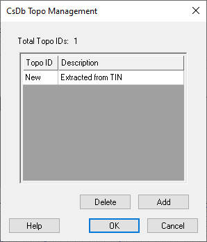
The CsDb Topo Management dialog is accessed via the Topo ID button in the Assign Cross Section dialog. It displays a table of defined topo IDs in the database.
- Above the table is a count of the Total Topo IDs.
- The table of IDs has columns for Topo ID and Description.
- Use the Add button to create a new topo ID entry in the table.
- Use the Delete button to delete the selected topo ID entry from the table.
Line Property Types Dialog
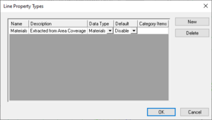
The Line Property Types dialog is accessed via the Topo ID button in the Assign Cross Section dialog. The Line Property Types dialog displays a table of defined material types in the database. The following columns are defined in the table:
- Name - The name of the line property type. This field can be edited.
- Description - A brief description of the line property type. This field can be edited.
- Data Type - Select one of four options from the drop-down:
- "Float"
- "Integer"
- "Materials"
- "Enumerated"
- Default - This value type changes depending on the Data Type selected from the drop-down:
- "Float" - Enter a decimal value.
- "Integer" - Enter an integer value.
- "Materials" - Select from the values listed in the Property Categories dialog.
- "Enumerated" - Select from the values listed in the Property Categories dialog.
- Category Items - The Define... button is accessible only when "Enumerated" is selected from the Data Type drop-down. Clicking the Define... button brings up the Property Categories dialog.
New types can be created using the New button. Entries can be deleted using the Delete button.
Property Categories Dialog
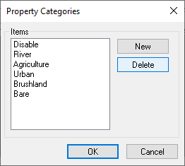
The Property Categories dialog is accessed via the Define... button in the Category Items column in the Line Property Types dialog. It is accessible only when "Enumerated" is selected from the Data Type drop-down. It displays a list of defined property categories in the database. The following categories appear in the Items section by default:
- "Disable"
- "River"
- "Agriculture"
- "Urban"
- "Brushland"
- "Bare"
New categories can be added by clicking the New button, double-clicking on the "New Item" entry, and entering the desired name. Categories can be deleted from the list by selecting the category and clicking Delete.
Point Property Types Dialog
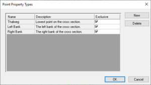
The Point Property Types dialog is accessed via the Pt Prop Types button in the Assign Cross Section dialog. It displays a table of defined point types in the database. The columns are:
- Name - The name of the type. The names for user-created types can be edited.
- Description - A brief description of the type. The description for user-created types can be edited.
- Exclusive - If this box is checked, there can only be one entry of that type on a cross section. See below for more details.
New point property types can be created by clicking New and editing the Name, Description, and Exclusive columns for the new entry. Though other properties can be defined, they are not mapped or saved to hydraulic models from within WMS. The Delete button can be used to delete user-created types.
Editing Cross Sections
After creating a cross section, additional refinement editing may need to be completed prior to using them for hydraulic modeling.
Cross sections can be edited in the following ways:
- Click the Edit button in the Assign Cross Section dialog.
- Open a cross section database for editing (or create a new database) using the Manage Cross Sections command.
Cross Section Attributes Dialog
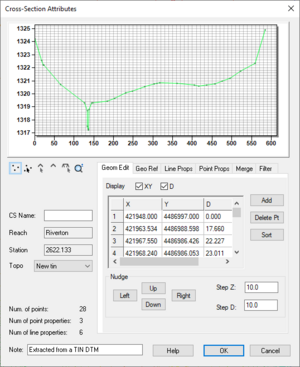
The Cross Section Attributes dialog is accessed by clicking the Edit button in the Assign Cross Section dialog or in the Manage Cross Sections dialog. This dialog allows cross section attributes to be modified as project needs dictate.
At the top of the dialog is a plot of the selected cross section. A toolbar is visible when the Geom Edit tab is selected.
The following tabs are located in the bottom right section of the dialog:
- Geom Edit - This tab is displayed by default when the Cross Section Attributes dialog opens.
- Geo Ref
- Line Props
- Point Props
- Merge
- Filter
At the bottom left of the dialog are the following items:
- CS Name - The name of the selected cross section. This field is editable and can be left blank.
- Reach - The name of the reach on which the cross section is found. This field is not editable.
- Station - The elevation of the station corresponding to the cross section.
- Topo - A drop-down list all of topographic datasets in the project. The name of the topographic data used to extract the cross section (if applicable) will be selected.
- Num. of points - The number of points on the cross section arc.
- Num of point properties - The number of defined point properties.
- Num of line properties - The number of defined line properties.
- Note - A note field. This field is editable and can be left blank.
Not all of these attributes are critical for the development of a hydraulic model, but they are useful in managing the cross section within a database.
The following tools are found at the bottom left of the plot except when the Geo Ref tab is selected:
 Add Point - Adds a new point to the plot.
 Select Point - Selects a point on the plot.
 Select Breakpoint - Selects a breakpoint on the plot.
 Insert Breakpoint - Inserts a breakpoint into the plot.
 Select Line Property - Selects a line property.
 Zoom Tool - Zoom in or out on a specific location in the plot.
Editing Geometry
The Geom Edit tab allows cross section points to be added and the values of those points to be edited. XY values are available when the actual 3D position of each point on the cross section is known. The more traditional D-Z pairs define the distance from the starting point and a corresponding elevation.
The options on the Geom Edit tab are:
- Display - The XY and D columns in the spreadsheet can be turned on or off.
- The spreadsheet displays columns containing values for X, Y, D, and Z.
- The Add button adds a new point to the cross section arc and a corresponding row to the spreadsheet.
- The Delete Pt button removes the selected point from the cross section arc, also removing the corresponding row from the spreadsheet.
- The Sort button sorts the spreadsheet in ascending order based on the value in the X column.
The Nudge section has directional buttons that move the selected point Up, Down, Left, or Right based on the values entered in the Step Z and Step D fields.
Geo-Referencing
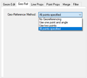
The Geo Ref tab has a Geo-Reference Method drop-down with the following options:
- "No Georeferencing"
- "Use one point and angle" - Enter X, Y, and D values in the Point section, an Angle, and then click Apply. Use this method if the centerline location is known and some angle relative to it needs to be defined
- "Use two points" - Enter X, Y, and D values in both the Primary Point and Secondary Point sections, then click Apply. These points are the coordinates for the beginning and ending locations along the defined cross section.
- "All points specified" - Extracted cross sections will be of this type.
Geo-referencing information provides the spatial (xy) location of the cross section and included geometry. This information is inherent in the 3D coordinates when extracting cross sections from a digital terrain model. However, if the cross section geometry is taken from a survey, the actual xyz coordinates of the points may not be known. In order to use the data within WMS for floodplain delineation, a proper geo-reference must be provided.
Line Properties
The Line Props tab allows for the defining of segments of material properties along the cross section. If an area property coverage was used during extraction from a digital terrain model, these properties are automatically marked and defined. They can be manually adjusted and managed from this tab.
The following items are found here:
- Type - A drop-down to select the type of line property. "Materials" is the default and is often the only option.
- The Edit Prop types button opens the Line Property Types dialog.
- The Delete button is used to delete the selected entry from the spreadsheet.
The spreadsheet has three columns:
- From - Defines the beginning location of the segment. This field is editable.
- To - Defines the ending location of the segment. This field is editable.
- Value - Defines the material type. If the material type is incorrect, a different type can be selected from the drop-down here.
Point Properties
The Point Props tab allows the point properties on the cross section to be edited. By default, these properties include "Thalweg" (the lowest elevation), "Left Bank", and "Right Bank" (determined by appropriate breaks in elevation/slope). When using a centerline and bank line arcs from a 1D Hydraulic Centerline coverage during extraction, these points are automatically marked. The Auto Mark button allows this process to be initiated manually.
The buttons along the right side are:
- Prop types - Opens the Point Property Types dialog.
- Add - Adds a new entry to the spreadsheet. NOTE: When adding new entries, be aware that some point property types are exclusive, meaning only one can exist per cross section.
- Delete - Deletes the selected entry from the spreadsheet.
- Sort - Sorts the entries in the spreadsheet in ascending order based on the measure column.
The measure column lists the distance along the cross section to the point. The Type column contains a drop-down allowing the point property type to be selected.
Merging
The Merge tab allows two cross sections to be merged. For example, if a terrain model does not contain enough detail to define the cross section of the river, a more detailed survey cross section could be inserted and merged using the tools on this tab.
NOTE: When merging cross sections, the new cross section must be created in a new cross section database before being merged with an existing cross section database.
The Load/Insert CS button brings up the Assign Cross Section dialog. Once the desired cross section has been imported and/or selected, click OK to return. The database will be displayed to the right of the CS ID to the right of the Load/Insert CS button.
The Alignment section allows the selection of where the two cross sections are aligned:
- "Left End"
- "Left Bank"
- "Thalweg"
- "Right Bank"
- "Right End"
An Offset can be specified. The offset uses the units set for the project. The imported cross section can be nudged Up, Down, Left, or Right based on the values entered in the Step Z and Step D fields. The Reset Changes button resets the nudging.
Below the Alignment section, the Merge drop-down offers the following options:
- "Insert All"
- "Insert Channel"
- "Blend Banks"
- "Blend All"
Clicking the Apply button applies any changes made and updates cross section.
Filtering
The Filter tab allows specifying rules for filtering "insignificant" points along the cross section in the case where there are more points defining the cross section than are necessary (or that the hydraulic model is capable of processing). This can be particularly important when extracting cross sections from a dense digital terrain model.
The Criteria section allows selecting from the following options:
- Angle or Distance
- Tolerance or Number Points
The Points drop-down contains the following options:
- "All"
- "Channel"
- "Overbanks"
Turning on the Lock points with point properties within a distance option allows a Distance to be set. Clicking the Apply button applies any changes made.
Extracting Cross Sections
The Extract Cross Sections command in the River Tools menu brings up the Extract Cross Sections dialog. When extracting cross sections they are saved to a new (or existing) database file. This database was the basis for the development of the cross section data in the ArcHydro data model. Cross sections in the database can be used for the development of hydraulic models such as HEC-RAS.
The Extract Cross Sections dialog uses the cross section arcs and a digital terrain model (either a TIN or a DEM) to extract the elevations at vertices of the feature arc cross sections, or at the intersection points with the triangles. There are three sections in this dialog:
- Cross sections
- Cross sections for individual arcs may be extracted by selecting the arc(s) before choosing the Extract Cross Sections command. If no cross sections are selected, then only the Use all cross sections option is available.
- Generate point properties
- Point properties (thalweg, left bank, right bank) can be defined from a 1D-Hydraulic centerline coverage, or by AutoMark. The AutoMark option examines the elevations of the extracted cross sections and infers the thalweg (low point) and the left and right bank points (change of slope) automatically. Selecting None means no point properties will be generated.
- Generate line properties
- Selecting Material zones determines the line properties from the area property coverage selected in the drop-down by intersecting the cross section arcs with the area property polygons and marking them in the cross section database. Selecting Manning's n value generates the line properties based on the Manning's n value entered. Selecting None means no line properties will be generated.
When OK is clicked, a popup will ask whether to extract the cross sections from a DEM or a TIN.
WMS stores all of the cross section information in a text database file. The cross section database can be edited independently using the Cross Section Attributes dialog. Extracting cross sections with feature arcs is only way to generate cross section information. They also can be imported from spreadsheet files (cut and paste), or entered manually.
NOTE: When merging cross sections, the new cross section must be created in a new cross section database before being merged with an existing cross section database.
Managing Cross Sections
The Manage Cross Sections dialog can be accessed by selecting River Tools | Manage Cross Sections.... This dialog is similar to the Assign Cross Section dialog, and all of the commands are described there.
Related Topics
- 1D Hydraulic Centerline Coverage
- Area Property Coverage
- 1D Hydraulic Modeling (HEC-RAS)
- Interpolation of Results
- Hydraulic Modeling
WMS – Watershed Modeling System | ||
|---|---|---|
| Modules: | Terrain Data • Drainage • Map • Hydrologic Modeling • River • GIS • 2D Grid • 2D Scatter |  |
| Models: | CE-QUAL-W2 • GSSHA • HEC-1 • HEC-HMS • HEC-RAS • HSPF • MODRAT • NSS • OC Hydrograph • OC Rational • Rational • River Tools • Storm Drain • SMPDBK • SWMM • TR-20 • TR-55 | |
| Toolbars: | Modules • Macros • Units • Digitize • Static Tools • Dynamic Tools • Drawing • Get Data Tools | |
| Aquaveo | ||
