User:Rcorrigan/Sandboxing GMS Menus: Difference between revisions
No edit summary |
No edit summary |
||
| Line 1: | Line 1: | ||
The ''Edit'' | '''Preferences''' command brings up the ''Preferences'' dialog. | |||
The ''Edit'' | |||
==General== | |||
[[File:PreferencesGeneral.png|thumb|450 px|The ''Preference'' dialog showing the ''General'' tab]] | |||
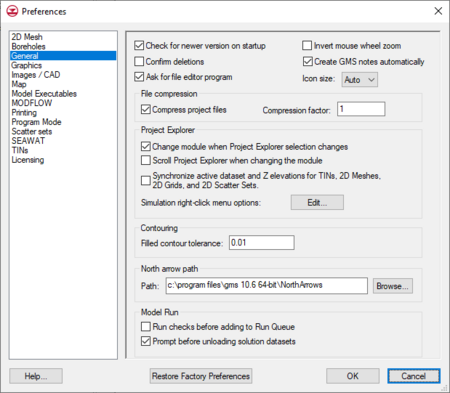
The ''General'' tab has all the of the general options in GMS. | |||
*''Show welcome dialog on startup'' – When turned off, the welcome dialog will not appear when starting GMS. | |||
*''Check for newer version on startup'' – When turned on, GMS will check aquaveo.com downloads page for the most recent release of GMS. If a new release is found, a prompt will appear asking if wanting to download the newer release. | |||
*''Confirm Deletions'' – Choose whether or not to be prompted to confirm the deletion whenever a set of selected objects is about to be deleted. This is meant to ensure that objects are not deleted accidentally. | |||
*''Ask for file editor program'' | |||
<!-- This option is not available in v10.0 and above | |||
*''Show new project wizard on startup'' – Shows the ''New Project'' dialog on startup. --> | |||
*''Invert mouse wheel zoom'' – Changes direction of the zoom with the mouse wheel | |||
*''Create GMS notes automatically'' – When on, certain actions will cause [[GMS:Notes#Automatic_Notes|notes]] to automatically generated. | |||
*''Icon size'' – Specifies the display size for icons. | |||
**"Auto" – The default icon display size. | |||
**"Small" – Causes the icons to be displayed at a smaller size; around 9 pixels wide. | |||
; | **"Large" – Causes the icons to be displayed at a larger size; around 27 pixels wide. | ||
Sections: | |||
; [[GMS: | *''File compression'' – Use compression when saving XMDF files. The compression factor can be specified. | ||
; | *''[[GMS:Project Explorer|Project Explorer]]'' – Allows modifying preferences related to the Project Explorer. | ||
; | **''Change Module when tree selection changes'' – Changes the current module when a item is selected in the Project Explorer. This option is on by default. | ||
**''Scroll Project Explorer when changing module'' – Ensures the visibility of the tree item objects in a module when the module is changed. | |||
**''Synchronize active dataset and Z elevations for TINs, 2D Meshes, 2D Grids, and 2D Scatter Sets'' | |||
; | *''Contouring'' – Allows entering a filled contour tolerance. | ||
*''North arrow path'' – Specify the path to the folder containing the North Arrows. | |||
*''Help'' – Options to use local help or online help. Online help is the default option. | |||
Buttons at the bottom: | |||
*'''Help...''' – Specify to use either a local help file or the online help file when clicking on the '''Help''' button in any dialog. | |||
*'''Restore Factory Preferences''' – Reverts all settings to the factory defaults. | |||
*'''OK''' – Accepts the settings as selected and entered and closes the ''Preferences'' dialog. | |||
*'''Cancel''' – Close the ''Preferences'' dialog without saving any changes to the settings. | |||
{{-}} | |||
==Model Executables== | |||
; [[GMS: | [[File:PreferencesModEx.png|thumb|450 px|The ''Preferences'' dialog showing the ''Models'' options]] | ||
The ''Models'' page allows specifying the location of model executables, as well as the option to use the Model Wrapper. | |||
*''Model Wrapper'' | |||
:: GMS is a pre- and post-processor for [[GMS:Numerical Models|Numerical Models]]. Most of these numerical models are run externally in the DOS environment. The default option is to use the Model Wrapper. The Model Wrapper "wraps" itself around the same DOS executables and gives more model feedback including graphs and tables. The Model Wrapper includes a toggle box in the bottom left that, when checked and after exiting the Model Wrapper, GMS will automatically read in the results of the solution. This toggle will only be checked by default if the model converged. The option to use the Model Wrapper or the old DOS view is included in the ''Preferences'' dialog. Certain models, including [[GMS:Stochastic Modeling|Stochastic]] and inverse modeling, can only be run using the Model Wrapper. | |||
Parallel versions of MODFLOW-2000, MODFLOW-2005, and SEAWAT are shipped with GMS to run simulations. Beginning with version 8, GMS ships parallel versions where the SAMG solver has been parallelized. Even when this option is on, when running Parallel PEST with MODFLOW the serial (non-parallel) version of MODFLOW will be used since the Parallel PEST will use all of the available cores on the computer with the serial version. Also see [[GMS:Preferences#MODFLOW|MODFLOW preferences]] for an option to turn on or off the parallel version. | |||
{{-}} | |||
==MODFLOW== | |||
[[File:PreferencesMODFLOW.png|thumb|450 px|The ''Preferences'' dialog showing the ''MODFLOW'' tab.]] | |||
The ''MODFLOW'' page has options related to the MODFLOW interface in GMS. | |||
*''Reverse mini-grid increment'' | |||
::The default functionality of the arrows next to the edit field on the mini-grid tool bar is for the up arrow to increase the layer number and for the down arrow to decrease the layer number. This option changes direction of the arrows so that down will increase the layer number and up will decrease the layer number. | |||
*''Compress MODFLOW H5 files'' | |||
::This option will force the H5 files saved with MODFLOW to be compressed. Generally this option should be turned on. | |||
*''Create h5 copy of head solution'' | |||
::Turning on this option can speed up reading the MODFLOW head solution especially when there are a large number of stress periods. When this option is on, GMS writes an HDF5 copy of the MODFLOW head solution upon reading it the first time. The following times GMS reads the head solution, it doesn't take as much time. | |||
*''Create cell summary text file'' | |||
::A text file is created when reading the MODFLOW head file that provides a summary of the the number of active, inactive, dry, and flooded cells at each output time of the simulation. The text file is added to the MODFLOW solution and can be opened from the Project Explorer. | |||
*''Save copy of MODFLOW simulation in native text format'' | |||
::This option will create an additional MODFLOW directory when the GMS project is saved that will contain native MODFLOW text files of the MODFLOW simulation. The new directory will be named as follows ''myProject''_MODFLOW_text. There are three additional preferences with this option: all arrays be written internally in the MODFLOW files (default option), all arrays are external from the MODFLOW files, or all arrays are external and are placed in a directory named ''arrays''. | |||
::External arrays are placed in their own text files and are named as follows ''myProject_array_PACKAGE_VARIABLE_LAYERorSP''. For example the ibound array for layer 1 would have the following name myProject_array_BAS_IBOUND_1.txt. The recharge array for stress period 3 would have the following name myProject_array_RCH_RECH_3.txt. | |||
*''Use custom Run dialog when running MODFLOW'' | |||
::This option will bring up the [[GMS:Custom Run MODFLOW|Custom Run MODFLOW]] dialog when the ''MODFLOW'' | '''Run MODFLOW''' menu command is selected. | |||
*''Default version of MODFLOW to run'' | |||
::Allows selecting the version of MODFLOW to be used as a default when GMS is started. | |||
*''Double precision'' | |||
::When this option is on, GMS will use the double precision version of MODFLOW to run simulations. By default this option is off and GMS uses the single precision version of MODFLOW. | |||
*''Parallel'' (not used by Parallel PEST) | |||
::When this option is on, GMS will use the parallel version of MODFLOW to run simulations. Beginning with version 8, GMS ships parallel versions of MODFLOW where the SAMG solver has been parallelized. Even when this option is on, Parallel PEST will use the serial (non-parallel) version of MODFLOW since the Parallel PEST will use all of the available cores on the computer. | |||
{{-}} | |||
==Images / CAD== | |||
*''Draw Order'' | |||
::Allows determining the vertical location of objects when being drawn. | |||
*''Bitmap Scale Factor'' | |||
::When the copy command is selected, a bitmap image of the screen is placed on the clipboard. The scale factor can be used to increase :or decrease the resolution of the bitmap. This scale factor also applies when saving the image as a bitmap. | |||
*''CAD Symbol Size'' | |||
::The size of the CAD symbol display can be specified. | |||
:[[File:PreferencesImagesCAD.png|thumb|left|450 px|The ''Preferences'' dialog showing the ''Images / CAD'' tab]] | |||
{{-}} | |||
==Printing== | |||
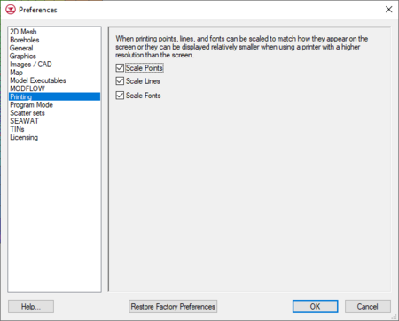
Specifies scaling points, lines, and fonts while printing. | |||
:[[File:PreferencesPrinting.png|thumb|left|450 px|The ''Preferences'' dialog showing the ''Printing'' tab]] | |||
{{-}} | |||
==Program Mode== | |||
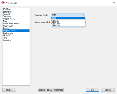
[[File:PreferencesProgMode.png|thumb|400 px|The ''Preferences'' dialog showing the ''Program Mode'' tab.]] | |||
GMS has the option of changing the "mode" or "skin" that GMS is running. The purpose of the mode is to simplify the items available in the interface. | |||
===Available Modes=== | |||
* GMS | |||
::This is the default mode. | |||
* GMS 2D | |||
::GMS 2D is for only using GMS to do seepage and slope stability. In GMS 2D mode the only tools that are available are the 2D mesh and the Map. There are several changes to the GMS interface when in this mode, including: | |||
::#Hiding of tools and modules not in use | |||
::#SEEP2D model automatically initialized from conceptual model | |||
::#SEEP2D boundary conditions automatically mapped from conceptual model (no need to run Map → SEEP2D) | |||
::#Easily create all coverage types in one step | |||
::#Feature object types automatically assigned based on coverage attributes | |||
::#Allow only one conceptual model | |||
When starting up in GMS 2D mode, a ''New Project'' dialog will appear. The following errors may also appear when opening some project files. These errors may state any of the following: | |||
<!-- Please do not change the following bullet points. These are exact quotes from the error messages. Thanks! --> | |||
:*Your project file contained more than one conceptual model. This version of GMS only supports one SEEP2D/UTEXAS conceptual model. The first encountered SEEP2D/UTEXAS conceptual model has been preserved and all other conceptual models have been removed from the project. | |||
:*Error. This requires the "MODFLOW" component. Your GMS license does not include this component. Contact your vendor if you would like to enable this feature. | |||
:*The project that you are reading does not have a SEEP2D/UTEXAS conceptual model. The project can not be loaded into this version of GMS. | |||
* GMS Site | |||
::GMS Site is for only using tools for site characterization. As such the tools available in this mode are TINs, Boreholes, Solids, 2D Scatter, and Map. These tools can be used to construct solid models of stratigraphy. | |||
* TPROGS | |||
::[[GMS:T-PROGS|T-PROGS]] is used to perform transition probability geostatistics on borehole data. | |||
===Caveats=== | |||
When GMS is running in a particular mode then only data associated with the available tools will be read into GMS. For example, if having a GMS project file that contains a 3D Grid, and running in "GMS 2D" mode then when reading in the project file a message will appear stating that GMS is not enabled to read in 3D Grid data. The only data that will read into GMS in "GMS 2D" mode is data associate with the 2D Mesh and the Map. | |||
{{-}} | |||
==Map== | |||
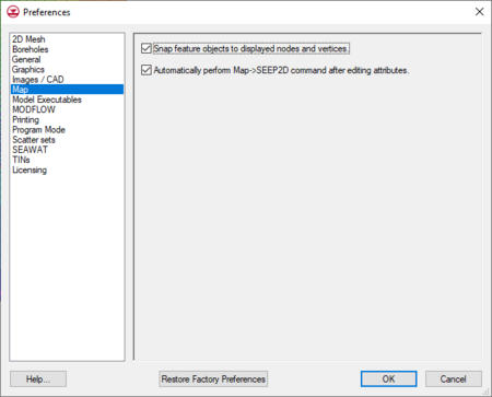
Gives the option to automatically perform the '''Map→SEEP2D''' command. | |||
:[[File:PreferencesMap.png|thumb|left|450 px|The ''Preferences'' dialog showing the ''Map'' tab.]] | |||
{{-}} | |||
==TINs== | |||
The ''TINs'' tab has the following options: | |||
*Vertex options | |||
**Retriangulate after deleting | |||
***Confirm z-value | |||
***Interpolate for default z on interior | |||
***Extrapolate for default z on exterior | |||
**Breakline options | |||
***Add supplementary points | |||
***Swap edges | |||
*Minimum length ratio | |||
For more detailed information, see [[GMS:TIN Settings|TIN Settings]]. | |||
{{-}} | |||
==Boreholes== | |||
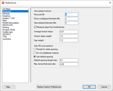
[[File:PreferencesBoreholes.png|thumb|450 px|The ''Prefences'' dialog showing the ''Borehole'' tab.]] | |||
*Auto-assign horizons | |||
::Rows per lift | |||
::Row overlapped between lifts | |||
::Sets retained between lifts | |||
*Measure slope from borehole tips | |||
::Average horizon slope | |||
::Horizon slope weight | |||
::Gap weight | |||
*Auto-Fill cross sections | |||
**Prompt for vertex spacing | |||
**Do not redistribute vertices | |||
**Use default spacing | |||
::Default spacing/length ratio | |||
::Max. lense thickness ratio | |||
{{-}} | |||
==Scatter sets== | |||
*2D scatter | |||
**Default dataset value | |||
**Confirm dateset value | |||
*3D scatter | |||
**Default dataset value | |||
**Default Z value | |||
**Confirm dateset value | |||
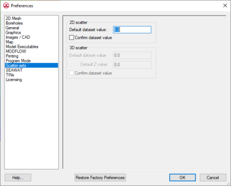
:[[File:PreferencesScatterSet.png|thumb|left|450 px|The ''Preferences'' dialog showing the ''Scatter Sets'' tab.]] | |||
{{-}} | |||
==2D Mesh== | |||
The ''2D Mesh'' tab has the following options: | |||
*Interpolate for default z on interior | |||
::Default z (ft) | |||
*Assign default z-value | |||
*Prompt for z-value | |||
*Insert nodes into triangulated mesh | |||
*Check for coincident nodes | |||
*Retriangulate voids when deleting | |||
::Thin triangle aspect ratio | |||
For more information, see [[GMS:2D Mesh Settings|2D Mesh Settings]]. | |||
{{-}} | |||
==Graphics== | |||
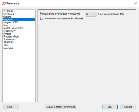
*''Multisampling level'' – Bigger numbers result in smoother, antialiased graphics. 0 = no multisampling, 16 = maximum multisampling. If this option is changed, GMS must be restarted before the change will take effect. | |||
*''Use smooth fonts'' – anti-alias fonts | |||
'''''Obsolete Options''''' | |||
The following options are not in use in current versions of GMS, but apply to older versions. | |||
*Ask which library to use if system does not support all functionality | |||
*Autoselect the software library if system does support all functionality | |||
*Always use system library like a dedicated GPU (may not support all features) | |||
*Always use software library on the CPU (may be slower) | |||
:[[File:PreferencesGraphics.png|thumb|left|450 px|The ''Preferences'' dialog showing the ''Graphics'' tab]] | |||
{{-}} | |||
==Licensing== | |||
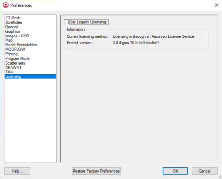
This tab shows information about the application license. | |||
*''Use Legacy Licensing'' – Turning on will revert to using older licenses. | |||
*''Information'' – Shows information about the license being used. | |||
:[[File:PreferencesLicensing.png|thumb|left|450 px|The ''Preferences'' dialog showing the ''Licensing'' tab]] | |||
{{-}} | |||
==Related Topics== | ==Related Topics== | ||
* [[GMS: | *[[GMS:Edit Menu|Edit Menu]] | ||
{{Navbox GMS}} | {{Navbox GMS}} | ||
[[Category:GMS | |||
[[Category: | [[Category:GMS Preference Dialogs]] | ||
[[Category:Preferences|G]] | |||
[[File:GMSunits.png|thumb|250 px|The ''Units'' dialog.]] | [[File:GMSunits.png|thumb|250 px|The ''Units'' dialog.]] | ||
Revision as of 17:25, 14 March 2022
The Edit | Preferences command brings up the Preferences dialog.
General
The General tab has all the of the general options in GMS.
- Show welcome dialog on startup – When turned off, the welcome dialog will not appear when starting GMS.
- Check for newer version on startup – When turned on, GMS will check aquaveo.com downloads page for the most recent release of GMS. If a new release is found, a prompt will appear asking if wanting to download the newer release.
- Confirm Deletions – Choose whether or not to be prompted to confirm the deletion whenever a set of selected objects is about to be deleted. This is meant to ensure that objects are not deleted accidentally.
- Ask for file editor program
- Invert mouse wheel zoom – Changes direction of the zoom with the mouse wheel
- Create GMS notes automatically – When on, certain actions will cause notes to automatically generated.
- Icon size – Specifies the display size for icons.
- "Auto" – The default icon display size.
- "Small" – Causes the icons to be displayed at a smaller size; around 9 pixels wide.
- "Large" – Causes the icons to be displayed at a larger size; around 27 pixels wide.
Sections:
- File compression – Use compression when saving XMDF files. The compression factor can be specified.
- Project Explorer – Allows modifying preferences related to the Project Explorer.
- Change Module when tree selection changes – Changes the current module when a item is selected in the Project Explorer. This option is on by default.
- Scroll Project Explorer when changing module – Ensures the visibility of the tree item objects in a module when the module is changed.
- Synchronize active dataset and Z elevations for TINs, 2D Meshes, 2D Grids, and 2D Scatter Sets
- Contouring – Allows entering a filled contour tolerance.
- North arrow path – Specify the path to the folder containing the North Arrows.
- Help – Options to use local help or online help. Online help is the default option.
Buttons at the bottom:
- Help... – Specify to use either a local help file or the online help file when clicking on the Help button in any dialog.
- Restore Factory Preferences – Reverts all settings to the factory defaults.
- OK – Accepts the settings as selected and entered and closes the Preferences dialog.
- Cancel – Close the Preferences dialog without saving any changes to the settings.
Model Executables
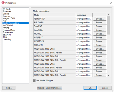
The Models page allows specifying the location of model executables, as well as the option to use the Model Wrapper.
- Model Wrapper
- GMS is a pre- and post-processor for Numerical Models. Most of these numerical models are run externally in the DOS environment. The default option is to use the Model Wrapper. The Model Wrapper "wraps" itself around the same DOS executables and gives more model feedback including graphs and tables. The Model Wrapper includes a toggle box in the bottom left that, when checked and after exiting the Model Wrapper, GMS will automatically read in the results of the solution. This toggle will only be checked by default if the model converged. The option to use the Model Wrapper or the old DOS view is included in the Preferences dialog. Certain models, including Stochastic and inverse modeling, can only be run using the Model Wrapper.
Parallel versions of MODFLOW-2000, MODFLOW-2005, and SEAWAT are shipped with GMS to run simulations. Beginning with version 8, GMS ships parallel versions where the SAMG solver has been parallelized. Even when this option is on, when running Parallel PEST with MODFLOW the serial (non-parallel) version of MODFLOW will be used since the Parallel PEST will use all of the available cores on the computer with the serial version. Also see MODFLOW preferences for an option to turn on or off the parallel version.
MODFLOW
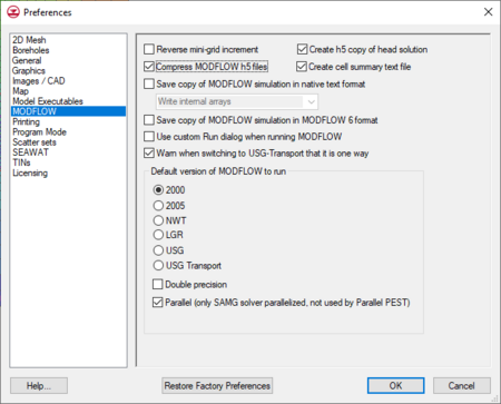
The MODFLOW page has options related to the MODFLOW interface in GMS.
- Reverse mini-grid increment
- The default functionality of the arrows next to the edit field on the mini-grid tool bar is for the up arrow to increase the layer number and for the down arrow to decrease the layer number. This option changes direction of the arrows so that down will increase the layer number and up will decrease the layer number.
- Compress MODFLOW H5 files
- This option will force the H5 files saved with MODFLOW to be compressed. Generally this option should be turned on.
- Create h5 copy of head solution
- Turning on this option can speed up reading the MODFLOW head solution especially when there are a large number of stress periods. When this option is on, GMS writes an HDF5 copy of the MODFLOW head solution upon reading it the first time. The following times GMS reads the head solution, it doesn't take as much time.
- Create cell summary text file
- A text file is created when reading the MODFLOW head file that provides a summary of the the number of active, inactive, dry, and flooded cells at each output time of the simulation. The text file is added to the MODFLOW solution and can be opened from the Project Explorer.
- Save copy of MODFLOW simulation in native text format
- This option will create an additional MODFLOW directory when the GMS project is saved that will contain native MODFLOW text files of the MODFLOW simulation. The new directory will be named as follows myProject_MODFLOW_text. There are three additional preferences with this option: all arrays be written internally in the MODFLOW files (default option), all arrays are external from the MODFLOW files, or all arrays are external and are placed in a directory named arrays.
- External arrays are placed in their own text files and are named as follows myProject_array_PACKAGE_VARIABLE_LAYERorSP. For example the ibound array for layer 1 would have the following name myProject_array_BAS_IBOUND_1.txt. The recharge array for stress period 3 would have the following name myProject_array_RCH_RECH_3.txt.
- Use custom Run dialog when running MODFLOW
- This option will bring up the Custom Run MODFLOW dialog when the MODFLOW | Run MODFLOW menu command is selected.
- Default version of MODFLOW to run
- Allows selecting the version of MODFLOW to be used as a default when GMS is started.
- Double precision
- When this option is on, GMS will use the double precision version of MODFLOW to run simulations. By default this option is off and GMS uses the single precision version of MODFLOW.
- Parallel (not used by Parallel PEST)
- When this option is on, GMS will use the parallel version of MODFLOW to run simulations. Beginning with version 8, GMS ships parallel versions of MODFLOW where the SAMG solver has been parallelized. Even when this option is on, Parallel PEST will use the serial (non-parallel) version of MODFLOW since the Parallel PEST will use all of the available cores on the computer.
Images / CAD
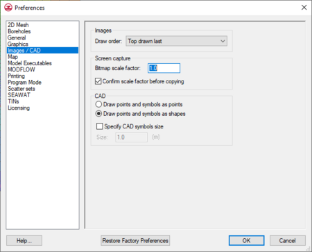
- Draw Order
- Allows determining the vertical location of objects when being drawn.
- Bitmap Scale Factor
- When the copy command is selected, a bitmap image of the screen is placed on the clipboard. The scale factor can be used to increase :or decrease the resolution of the bitmap. This scale factor also applies when saving the image as a bitmap.
- CAD Symbol Size
- The size of the CAD symbol display can be specified.
Printing
Specifies scaling points, lines, and fonts while printing.
Program Mode
GMS has the option of changing the "mode" or "skin" that GMS is running. The purpose of the mode is to simplify the items available in the interface.
Available Modes
- GMS
- This is the default mode.
- GMS 2D
- GMS 2D is for only using GMS to do seepage and slope stability. In GMS 2D mode the only tools that are available are the 2D mesh and the Map. There are several changes to the GMS interface when in this mode, including:
- Hiding of tools and modules not in use
- SEEP2D model automatically initialized from conceptual model
- SEEP2D boundary conditions automatically mapped from conceptual model (no need to run Map → SEEP2D)
- Easily create all coverage types in one step
- Feature object types automatically assigned based on coverage attributes
- Allow only one conceptual model
- GMS 2D is for only using GMS to do seepage and slope stability. In GMS 2D mode the only tools that are available are the 2D mesh and the Map. There are several changes to the GMS interface when in this mode, including:
When starting up in GMS 2D mode, a New Project dialog will appear. The following errors may also appear when opening some project files. These errors may state any of the following:
- Your project file contained more than one conceptual model. This version of GMS only supports one SEEP2D/UTEXAS conceptual model. The first encountered SEEP2D/UTEXAS conceptual model has been preserved and all other conceptual models have been removed from the project.
- Error. This requires the "MODFLOW" component. Your GMS license does not include this component. Contact your vendor if you would like to enable this feature.
- The project that you are reading does not have a SEEP2D/UTEXAS conceptual model. The project can not be loaded into this version of GMS.
- GMS Site
- GMS Site is for only using tools for site characterization. As such the tools available in this mode are TINs, Boreholes, Solids, 2D Scatter, and Map. These tools can be used to construct solid models of stratigraphy.
- TPROGS
- T-PROGS is used to perform transition probability geostatistics on borehole data.
Caveats
When GMS is running in a particular mode then only data associated with the available tools will be read into GMS. For example, if having a GMS project file that contains a 3D Grid, and running in "GMS 2D" mode then when reading in the project file a message will appear stating that GMS is not enabled to read in 3D Grid data. The only data that will read into GMS in "GMS 2D" mode is data associate with the 2D Mesh and the Map.
Map
Gives the option to automatically perform the Map→SEEP2D command.
TINs
The TINs tab has the following options:
- Vertex options
- Retriangulate after deleting
- Confirm z-value
- Interpolate for default z on interior
- Extrapolate for default z on exterior
- Breakline options
- Add supplementary points
- Swap edges
- Retriangulate after deleting
- Minimum length ratio
For more detailed information, see TIN Settings.
Boreholes
- Auto-assign horizons
- Rows per lift
- Row overlapped between lifts
- Sets retained between lifts
- Measure slope from borehole tips
- Average horizon slope
- Horizon slope weight
- Gap weight
- Auto-Fill cross sections
- Prompt for vertex spacing
- Do not redistribute vertices
- Use default spacing
- Default spacing/length ratio
- Max. lense thickness ratio
Scatter sets
- 2D scatter
- Default dataset value
- Confirm dateset value
- 3D scatter
- Default dataset value
- Default Z value
- Confirm dateset value
2D Mesh
The 2D Mesh tab has the following options:
- Interpolate for default z on interior
- Default z (ft)
- Assign default z-value
- Prompt for z-value
- Insert nodes into triangulated mesh
- Check for coincident nodes
- Retriangulate voids when deleting
- Thin triangle aspect ratio
For more information, see 2D Mesh Settings.
Graphics
- Multisampling level – Bigger numbers result in smoother, antialiased graphics. 0 = no multisampling, 16 = maximum multisampling. If this option is changed, GMS must be restarted before the change will take effect.
- Use smooth fonts – anti-alias fonts
Obsolete Options
The following options are not in use in current versions of GMS, but apply to older versions.
- Ask which library to use if system does not support all functionality
- Autoselect the software library if system does support all functionality
- Always use system library like a dedicated GPU (may not support all features)
- Always use software library on the CPU (may be slower)
Licensing
This tab shows information about the application license.
- Use Legacy Licensing – Turning on will revert to using older licenses.
- Information – Shows information about the license being used.
Related Topics
GMS – Groundwater Modeling System | ||
|---|---|---|
| Modules: | 2D Grid • 2D Mesh • 2D Scatter Point • 3D Grid • 3D Mesh • 3D Scatter Point • Boreholes • GIS • Map • Solid • TINs • UGrids | |
| Models: | FEFLOW • FEMWATER • HydroGeoSphere • MODAEM • MODFLOW • MODPATH • mod-PATH3DU • MT3DMS • MT3D-USGS • PEST • PHT3D • RT3D • SEAM3D • SEAWAT • SEEP2D • T-PROGS • ZONEBUDGET | |
| Aquaveo | ||
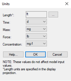
When building a ground water model, it is important to ensure that consistent units are used when entering model parameters. To simplify the management of model units, define the units for length, time, mass, force, and concentration in the Units dialog. A units label is placed next to each of the input fields in all the model dialogs in GMS where the units are known. For example, the units for hydraulic conductivity are length / time. If the length units are defined as "m" (meters) and the time units are defined as "d" (days) in the Units dialog, then the units string next to the hydraulic conductivity input field would be "m/d".
Length units are specified in the Display Projection dialog which is accessed by clicking on the ![]() button to the right.
button to the right.
Concentration units can be defined separately, and potentially inconsistently with, mass and length units. This allows for more flexibility but can also lead to confusion so use care when selecting concentration units.
The Units dialog is accessed by using the Units... command in the Edit menu.
Unit Conversion
Generally speaking, GMS does not convert quantities from one system of units to another. GMS only displays the chosen units to help in checking consistency. However, in a few places, GMS will use the currently defined units in its calculations. These include:
- in the FEMWATER Fluid Properties dialog,
- in the Curve Generator dialog,
- when calculating the stream stage constant when saving MODFLOW, and
- in the Measure tool.
See also
GMS – Groundwater Modeling System | ||
|---|---|---|
| Modules: | 2D Grid • 2D Mesh • 2D Scatter Point • 3D Grid • 3D Mesh • 3D Scatter Point • Boreholes • GIS • Map • Solid • TINs • UGrids | |
| Models: | FEFLOW • FEMWATER • HydroGeoSphere • MODAEM • MODFLOW • MODPATH • mod-PATH3DU • MT3DMS • MT3D-USGS • PEST • PHT3D • RT3D • SEAM3D • SEAWAT • SEEP2D • T-PROGS • ZONEBUDGET | |
| Aquaveo | ||
