WMS:Defining Roughness: Difference between revisions
From XMS Wiki
Jump to navigationJump to search
No edit summary |
|||
| (12 intermediate revisions by the same user not shown) | |||
| Line 1: | Line 1: | ||
Roughness values are determined for cross sections based on a set of material properties defined for the cross sections. Material properties are defined in a four step process. | Roughness values are determined for cross sections based on a set of material properties defined for the cross sections. Material properties are defined in a four step process. | ||
#Create a master set of materials (land use) types that define the possible choices to be found in the floodplain being modeled. Typically, define as many materials as there will be defined manning's roughness values. This is done using the '''Materials''' command in the ''SMPDBK'' menu. | |||
#:[[Image:WMSMaterialsData.png|350 px]] | |||
:[[Image: | #Create an Area Property Coverage that consists of polygons corresponding to the different land use (roughness) types found in the floodplain. After building the coverage, define each polygon attribute by double-clicking on the polygon and assigning the appropriate roughness value. Generally these polygons will be a more generalized version of a land use map. | ||
#:[[Image:SMPDBK2.png|300 px]] | |||
#Define the manning's roughness values that correspond to each material property. This dialog is accessed from the ''SMPDBK'' menu using the '''Material Properties''' command. | |||
#:[[File:WMS HEC RAS MP.png|150 px]] | |||
:[[Image: | #Assign the created materials properties to the cross section database being used. This will make sure that properties mapped to the cross sections when cut from a digital terrain model have a roughness value assigned. This is done using the '''Model Control''' option in the ''SMPDBK'' menu. | ||
#:[[Image:HEC-RES MC.png|180 px]] | |||
:[[ | |||
:[[Image: | |||
When WMS writes the SMPDBK input file, average roughness values are computed based on the conveyance for the elevation/top-width increment. | When WMS writes the SMPDBK input file, average roughness values are computed based on the conveyance for the elevation/top-width increment. | ||
| Line 26: | Line 19: | ||
{{WMSMain}} | {{WMSMain}} | ||
[[Category:SMPDBK|D]] | |||
[[Category:WMS Dialogs|Defining]] | |||
[[Category:SMPDBK Dialogs]] | |||
Latest revision as of 20:30, 8 June 2023
Roughness values are determined for cross sections based on a set of material properties defined for the cross sections. Material properties are defined in a four step process.
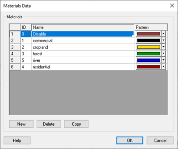
- Create a master set of materials (land use) types that define the possible choices to be found in the floodplain being modeled. Typically, define as many materials as there will be defined manning's roughness values. This is done using the Materials command in the SMPDBK menu.
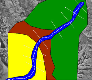
- Create an Area Property Coverage that consists of polygons corresponding to the different land use (roughness) types found in the floodplain. After building the coverage, define each polygon attribute by double-clicking on the polygon and assigning the appropriate roughness value. Generally these polygons will be a more generalized version of a land use map.
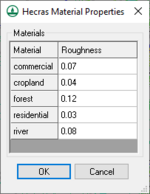
- Define the manning's roughness values that correspond to each material property. This dialog is accessed from the SMPDBK menu using the Material Properties command.
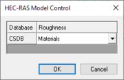
- Assign the created materials properties to the cross section database being used. This will make sure that properties mapped to the cross sections when cut from a digital terrain model have a roughness value assigned. This is done using the Model Control option in the SMPDBK menu.
When WMS writes the SMPDBK input file, average roughness values are computed based on the conveyance for the elevation/top-width increment.
Related Topics
WMS – Watershed Modeling System | ||
|---|---|---|
| Modules: | Terrain Data • Drainage • Map • Hydrologic Modeling • River • GIS • 2D Grid • 2D Scatter |  |
| Models: | CE-QUAL-W2 • GSSHA • HEC-1 • HEC-HMS • HEC-RAS • HSPF • MODRAT • NSS • OC Hydrograph • OC Rational • Rational • River Tools • Storm Drain • SMPDBK • SWMM • TR-20 • TR-55 | |
| Toolbars: | Modules • Macros • Units • Digitize • Static Tools • Dynamic Tools • Drawing • Get Data Tools | |
| Aquaveo | ||


