GMS:MNW1 Package
Conceptual Model
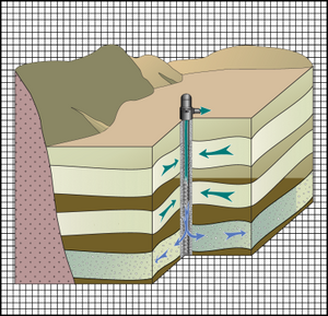
MNW1 wells can be modeled using points in a conceptual model. The user can specify the various MNW1 properties associated with points in a coverage. In addition, a multi-node MNW1 boundary condition can be created using the conceptual model approach. The easiest way to create a multi-node MNW1 boundary condition is to define a well screen associated with the MNW1 point that crosses multiple layers of the MODFLOW grid. Another method for creating a multi-node MNW1 boundary condition is to specify a common "Well ID" to group different points together. Thus, multiple points in the same or different coverages can be used to create multi-node MNW1 boundary conditions.
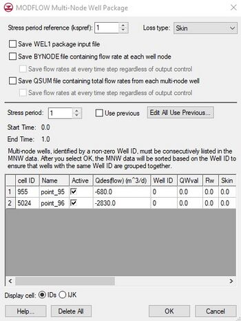
Multi-Node Well Package Dialog
The Multi-Node Well (MNW1) Package dialog allows the user to edit the location and the input values associated with each MNW boundary condition. MNW1 boundary conditions cannot be created or deleted from this dialog. They can be created and deleted via the Map → MODFLOW command, or by using the MODFLOW Source/Sink dialog. The package is also available in the MNW1 Package tutorial.
The upper section of the dialog controls global options for the package. The spreadsheet in the lower section of the dialog controls the boundary conditions that vary with each stress period. The user is referred to the MNW1 documentation for a full explanation of each of the inputs to the MNW1 boundary conditions. GMS has added the Name, Active, and Well ID fields. Name is a label used to identify a boundary condition. Active is a flag used to determine if the boundary condition is used during a particular stress period. The Well ID field is used to identify multi-node wells.
Notes
- ^ Halford, Keith J. (2002), User Guide for the Drawdown-Limited, Multi-Node Well (MNW) Package for the U.S. Geological Survey's Modular Three-Dimensional Finite-Difference Ground-Water Flow Model, Versions MODFLOW-96 and MODFLOW-2000. Open-File Report 02-293., Sacramento, California, http://pubs.usgs.gov/of/2002/ofr02293/text.pdf
GMS – Groundwater Modeling System | ||
|---|---|---|
| Modules: | 2D Grid • 2D Mesh • 2D Scatter Point • 3D Grid • 3D Mesh • 3D Scatter Point • Boreholes • GIS • Map • Solid • TINs • UGrids | |
| Models: | FEFLOW • FEMWATER • HydroGeoSphere • MODAEM • MODFLOW • MODPATH • mod-PATH3DU • MT3DMS • MT3D-USGS • PEST • PHT3D • RT3D • SEAM3D • SEAWAT • SEEP2D • T-PROGS • ZONEBUDGET | |
| Aquaveo | ||

