|
|
| Line 44: |
Line 44: |
| ==CLN Wells Dialog== | | ==CLN Wells Dialog== |
|
| |
|
| The ''MODFLOW CLN Wells Package'' is similar to the [[GMS:WEL_Package|WEL Package]] dialog. It is reached through the ''MODFLOW'' | ''Optional Packages'' | '''CLN Wel – CLN Well''' menu command. It allows CLN well flow rates to be viewed and edited, and CLN wells can also be deleted. The ''Cell ID'' table column is the CLN Process node ID of the well. | | The ''MODFLOW CLN Wells Package'' is similar to the [[GMS:WEL_Package|''WEL Package'']] dialog. It is reached through the ''MODFLOW'' | ''Optional Packages'' | '''CLN Wel – CLN Well''' menu command. It allows CLN well flow rates to be viewed and edited, and CLN wells can also be deleted. The ''Cell ID'' table column is the CLN Process node ID of the well. |
| [[File:CLN Wells.png|thumb|none|370 px|The ''MODFLOW CLN Wells Package'' dialog]] | | [[File:CLN Wells.png|thumb|none|370 px|The ''MODFLOW CLN Wells Package'' dialog]] |
|
| |
|
| MODFLOW |
|---|
| Pre-processing |
|---|
|
MODFLOW Commands |
|
Building a MODFLOW Model |
|
Map to MODFLOW |
|
Calibration |
|
Packages Supported in GMS |
|
Saving a MODFLOW Simulation |
|
Importing MODFLOW Files |
|
Unsupported MODFLOW Features |
|
Run MODFLOW |
| Post-processing |
|---|
|
MODFLOW Display Options |
|
MODFLOW Post-Processing Viewing Options |
|
Reading a MODFLOW Simulation |
| Tutorials |
|---|
| Packages |
|---|
| Flow: |
BCF6, HUF, LPF, UPW |
|---|
| Solvers: |
DE4, GMG, NWT, PCG,
PCGN, LMG, SIP, SOR,
SMS |
|---|
| Other: |
BAS6, BFH, CHD1, CLN,
DRN1, DRT1, EVT1, ETS1,
GAGE, GHB1, GNC, HFB1,
HUF, LAK3, MNW1, MNW2,
OUT1, RCH1, RIV1, SFR2,
STR1, SUB1, SWI2, WEL1,
UZF1 |
|---|
|
The Connected Linear Network (CLN) process was developed for MODFLOW-USG to model one dimensional connected features that are much smaller than a groundwater flow model's cells.[1] The CLN Process can be used to replace multi-cell wells that would use the MNW1 or MNW2 package in other versions of MODFLOW.
Conceptual Model
A CLN well can be added to a conceptual model by creating a point using the "Wells (CLN)" type. The geometry of the well screen can be set using the Use screen attribute for a single vertical screen. Otherwise, the generated well nodes include the grid layers specified for the coverage by its default layer range. For transient models, the CLN well node IBOUND values are disabled until the first stress period with a non-zero flow rate.
CLN Process Dialog
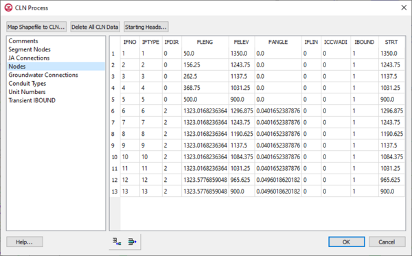
The CLN process values can be edited in the CLN Process dialog reached through the MODLFOW | Optional Packages | CLN – Connected Linear Network menu command. The dialog contains tables that can be accessed by selecting a table from the list at the left of the dialog.
- ClnText
- SegmentNodes – The CLN process contains nodes that can be connected together. Each connected nodes have a unique ClnSegmentId, and each node has a unique IFNO value.
- JAConnections – Allows editing the connectivity of nodes similar to the SegmentNodes table.
- Nodes – This table allows data for CLN nodes to be edited and viewed including the starting head and IBOUND values for each node.
- GwConnections – This table shows the connections between the CLN process and nodes and the groundwater process cells. The IGWNOD column contains the cell ID of the connected groundwater node.
- ConduitTypes – This table shows the conduit types generated for each CLN node and the associated mapped values for FRAD and CONDUITK previously entered in the Map module.
- UnitNumbers
- TransientIBOUND – Edits changing IBOUND values in transient models. This table can be edited when cells become active and inactive.
A detailed description of CLN process input is available with the MODFLOW-USG documentation available at the USGS MODFLOW-USG website.
MODFLOW
CLN Process dialog showing the
Nodes options
The
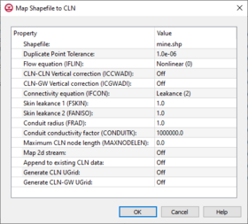
Map Shapefile to CLN dialog
Map Shapefile to CLN
The Connected Linear Network (CLN) process was developed for MODFLOW-USG to have the ability to model complex one-dimensional connected features that are much smaller than a groundwater flow model’s cells. A three-dimensional arc shapefile can be used to store the geometry and attributes of such a linear network.
Clicking the Map Shapefile to CLN button in the CLN Process dialog will first bring up a Select Arc Shapefile dialog. Once a shapefile has been selected, the Map Shapefile to CLN dialog will appear. The settings items in this dialog are used when attributes are not specified as arc attributes by the shapefile.
CLN Wells Dialog
The MODFLOW CLN Wells Package is similar to the WEL Package dialog. It is reached through the MODFLOW | Optional Packages | CLN Wel – CLN Well menu command. It allows CLN well flow rates to be viewed and edited, and CLN wells can also be deleted. The Cell ID table column is the CLN Process node ID of the well.
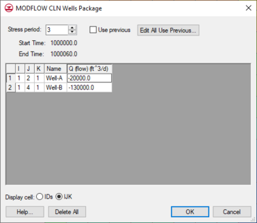
The
MODFLOW CLN Wells Package dialog
Notes
- ^ Panday, Sorab; Langevin, Christian D.; Niswonger, Richard G.; Ibaraki, Motomu; Hughes, Joseph D. (2013), MODFLOW-USG Version 1: An Unstructured Grid Version of MODFLOW for Simulation Groundwater Flow and Tightly Coupled Processes Using a Control Volume Finite-Difference Formulation: U.S. Geological Survey Techniques and Methods, Book 6, Chapter A45, Reston, Virginia, http://pubs.usgs.gov/tm/06/a45/pdf/tm6-A45.pdf


