SMS:Scatter Triangles Menu: Difference between revisions
| Line 5: | Line 5: | ||
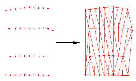
Scatter points or mesh nodes can be triangulated to form piecewise linear surfaces. For scattered data, these surfaces are also referred to as TINs (Triangular Irregular Networks). For mesh nodes, they form a finite element mesh. The points/nodes are connected into surfaces as scatter sets or meshes are created, but at times it may be necessary to reconnect the points (i.e. after deleting individual points/nodes or triangles/elements). New triangles are constructed in mass by triangulating a set of points when the Triangulate command from the Scatter Data menu is executed. The selected points are connected with a series of triangles. If points are not selected, then all points will be triangulated. | Scatter points or mesh nodes can be triangulated to form piecewise linear surfaces. For scattered data, these surfaces are also referred to as TINs (Triangular Irregular Networks). For mesh nodes, they form a finite element mesh. The points/nodes are connected into surfaces as scatter sets or meshes are created, but at times it may be necessary to reconnect the points (i.e. after deleting individual points/nodes or triangles/elements). New triangles are constructed in mass by triangulating a set of points when the Triangulate command from the Scatter Data menu is executed. The selected points are connected with a series of triangles. If points are not selected, then all points will be triangulated. | ||
[[File:Triangulate1.jpg|thumb|left | [[File:Triangulate1.jpg|thumb|none|left|450 px]] | ||
====Delaunay Criterion==== | ====Delaunay Criterion==== | ||
The resulting triangulation satisfies the Delauney criterion. The Delauney criterion ensures that no vertex lies within the interior of any of the circumcircles of the triangles in the network as shown below: | The resulting triangulation satisfies the Delauney criterion. The Delauney criterion ensures that no vertex lies within the interior of any of the circumcircles of the triangles in the network as shown below: | ||
[[File:Triangulate2.jpg|thumb|left | [[File:Triangulate2.jpg|thumb|none|left|300 px]] | ||
[[File:DelaunayCriterion.gif|thumb|left | [[File:DelaunayCriterion.gif|thumb|none|left|300 px]] | ||
Two Adjacent Triangles Which (a) Violate and (b) Honor the Delauney Criterion. | Two Adjacent Triangles Which (a) Violate and (b) Honor the Delauney Criterion. | ||
Revision as of 19:38, 17 December 2012
The items unique to the Scatter module are listed below. The menu items operate on the active scatter set unless otherwise noted:
General Commands
Triangulate
Scatter points or mesh nodes can be triangulated to form piecewise linear surfaces. For scattered data, these surfaces are also referred to as TINs (Triangular Irregular Networks). For mesh nodes, they form a finite element mesh. The points/nodes are connected into surfaces as scatter sets or meshes are created, but at times it may be necessary to reconnect the points (i.e. after deleting individual points/nodes or triangles/elements). New triangles are constructed in mass by triangulating a set of points when the Triangulate command from the Scatter Data menu is executed. The selected points are connected with a series of triangles. If points are not selected, then all points will be triangulated.
Delaunay Criterion
The resulting triangulation satisfies the Delauney criterion. The Delauney criterion ensures that no vertex lies within the interior of any of the circumcircles of the triangles in the network as shown below:
Two Adjacent Triangles Which (a) Violate and (b) Honor the Delauney Criterion.
The result of enforcing the Delauney criterion is that long thin triangles are avoided as much as possible.
Triangulate
The vertices associated with the active scatter set can be triangulated using the Triangulate command from the Triangles menu in the Scatter module. Mesh nodes (either the selected nodes, or all nodes) can be triangulated using the Triangulate command from the Elements menu in the 2D Mesh module.
Optimize Triangulation
At times, the user will perform manual mesh editing using the Swap Edge tool. This makes the Delauney criterion no longer hold. Selected elements can be returned to the Delauney state by choosing the Optimize Triangulation command from the Elements menu.
Select Thin Triangles
During the process of triangulation, a mesh of triangular elements is created around existing nodes. This usually creates triangular elements outside the desired mesh boundary. Many of these exterior triangles are very skinny, and some are virtually invisible. The Select Thin Triangles command from the Elements Menu finds and selects skinny triangular elements which are on the mesh boundary.
Thin triangles interior to the mesh will not be selected when this command is performed, since deletion of interior triangles would result in gaps in the mesh. After the thin triangles have been selected, they can be removed by selecting the Delete macro File:Delete icon.bmp.
Select/Delete Long Triangles
Related Topics
SMS Menu Bars | |
|---|---|
| Standard Menus: | File • Edit • Display • Window • Help |
| Module Menus: | 2D Mesh • Cartesian Grid • Curvilinear Grid • GIS • Map • Particle • Quadtree • Raster • Scatter |
| Model Menus: | ADCIRC • BOUSS-2D • CGWAVE • CMS-Flow • CMS-Wave • FESWMS • Generic Model • GenCade • PTM • RMA2 • RMA4 • SRH-2D • STWAVE • TUFLOW |
SMS – Surface-water Modeling System | ||
|---|---|---|
| Modules: | 1D Grid • Cartesian Grid • Curvilinear Grid • GIS • Map • Mesh • Particle • Quadtree • Raster • Scatter • UGrid |  |
| General Models: | 3D Structure • FVCOM • Generic • PTM | |
| Coastal Models: | ADCIRC • BOUSS-2D • CGWAVE • CMS-Flow • CMS-Wave • GenCade • STWAVE • WAM | |
| Riverine/Estuarine Models: | AdH • HEC-RAS • HYDRO AS-2D • RMA2 • RMA4 • SRH-2D • TUFLOW • TUFLOW FV | |
| Aquaveo • SMS Tutorials • SMS Workflows | ||

